This post is older than 2 years and might not be relevant anymore
More Info: Consider searching for newer posts

Using nRF52811 for direction finding

nRF52811 has only one receiver. Most accurate direction finding can be made based on estimation of phase difference between two signals received in two spaced antennas. Such phase difference can be accurately estimated if we take samples in two receiving channels at the same moment. So, two receiving channels shall have the same coherent LO source and samples shall be made synchronously. Correspondingly, I would like to ask have 3 questions:

1. Can we use two nRF52811 systems with the same coherent LO source?

2. Can we synchronize IQ sampling moments in both nRF52811 systems?

3. If question 1 and 2 are negative, what AOA estimation approach shall be used with nRF52811 ?

If my questions are incorrect, I would appreciate any clarifications regarding that.

Parents
  • Hi Vlad,

    "IQ sampling is made over demodulated signal having frequency of 250kHz or Since signal frequency is relatively low, samples taken in different antennas can be effectively synchronized."

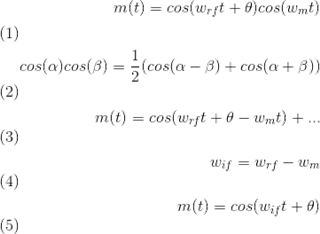
    No. While the baseband frequency is 250 kHz, the phase shifts seen by the antennas will be preserved from the baseband's perspective. If you do the math, a phase shift at RF will equate to the same phase shift at baseband. Dmitry was alluding to this earlier. See following:

    "3. If question 1 and 2 are negative, what AOA estimation approach shall be used with nRF52811 ?"

    Inferring from the product specification, section 6.14.12, or page 189, and that this is part of the Bluetooth specification, the transmitter appends a "continuous tone extension" to the end of a direction finding packet. The first part of the packet is a normal BLE packet, but then after the CRC, the transmitter continues transmitting the current bit it is on, which is a CW tone. It holds this tone for a duration configured by the receiver. The duration of the tone, according to the the details in the datasheet, consist of a guard time, and several switch slots, in that order. It is during the guard time that the receiver calibrates and locks its PLL, after which, disables the PLL feedback so the LO's phase can't change once we route another RF path from another antenna into the receiver - this is what is happening during the switch slots. The various RF paths from the different antennas are fed into the receiver, and the output of the IQ modulator will be indeed output phases equal to arctan(Q/I) relative to the antenna that was activated during the guard period. 

    Somebody please correct me if I am wrong.

    Yes, I agree that this is not the cutting edge MUSIC algorithm. But I have yet to try their implementation to give it a thumbs up or thumbs down as to whether or not it can be used practically.   

Reply
  • Hi Vlad,

    "IQ sampling is made over demodulated signal having frequency of 250kHz or Since signal frequency is relatively low, samples taken in different antennas can be effectively synchronized."

    No. While the baseband frequency is 250 kHz, the phase shifts seen by the antennas will be preserved from the baseband's perspective. If you do the math, a phase shift at RF will equate to the same phase shift at baseband. Dmitry was alluding to this earlier. See following:

    "3. If question 1 and 2 are negative, what AOA estimation approach shall be used with nRF52811 ?"

    Inferring from the product specification, section 6.14.12, or page 189, and that this is part of the Bluetooth specification, the transmitter appends a "continuous tone extension" to the end of a direction finding packet. The first part of the packet is a normal BLE packet, but then after the CRC, the transmitter continues transmitting the current bit it is on, which is a CW tone. It holds this tone for a duration configured by the receiver. The duration of the tone, according to the the details in the datasheet, consist of a guard time, and several switch slots, in that order. It is during the guard time that the receiver calibrates and locks its PLL, after which, disables the PLL feedback so the LO's phase can't change once we route another RF path from another antenna into the receiver - this is what is happening during the switch slots. The various RF paths from the different antennas are fed into the receiver, and the output of the IQ modulator will be indeed output phases equal to arctan(Q/I) relative to the antenna that was activated during the guard period. 

    Somebody please correct me if I am wrong.

    Yes, I agree that this is not the cutting edge MUSIC algorithm. But I have yet to try their implementation to give it a thumbs up or thumbs down as to whether or not it can be used practically.   

Children
  • Hi Robwasab,

    Thank you. As I see now,  I missed “The IQ samples are recorded with respect to the RX carrier frequency” sentence in the spec and decided the sampling is made over demodulated signal without referring to the carrier. Strange, the developers did not point me that out.  It is great if I was wrong. Hopefully PLL jitter will not make significant phase noise.

    “I agree that this is not the cutting edge MUSIC algorithm”

    MUSIC is a fundamental algorithm. It requires making distance between antennas not more the half of wavelength for unambiguous AOA detection.  Max distance between antennas in array defines the accuracy of AOA estimate. We need many antennas if we need accurate AOA estimation with MUSIC.  The more antennas, the more eigenvalues have to be calculated in the algorithm. Correspondingly, more resources and time for calculation are needed.  It affects the system throughput quite well. Other methods would be more effective in low cost applications. For instance, methods based on disambiguation from one baseline to another one.

Related