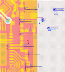
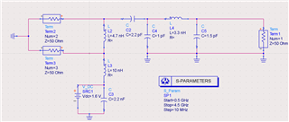
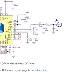
I simulated the balun of nrf51822 accroding to the referenced design of nrf51822 on the official website.
However,it showed the differential phase of the balun was not 180 degrees.
Please help me to find a solution,thanks.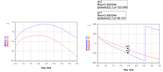
I simulated the balun of nrf51822 accroding to the referenced design of nrf51822 on the official website.
However,it showed the differential phase of the balun was not 180 degrees.
Please help me to find a solution,thanks.

 rly?
rly?