This post is older than 2 years and might not be relevant anymore
More Info: Consider searching for newer posts

Spurious Emission when the payload model is set to PRBS9

Dear All,

I tested spurious emission of Tx for FCC approval.

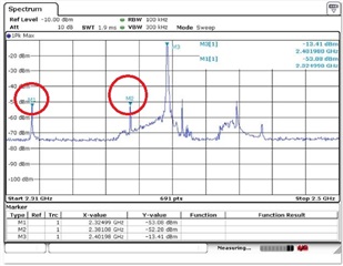
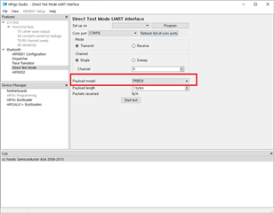
But, the spurious is occurring at 2.33GHz and 2.38GHz when the payload model is set to "PRBS9" as the below image.

There is no spurious emission when the payload model is set to "constant carrier".

Are this symptoms reasonable?

If not, please let me know the solution.

Please refer to the below information for out test conditions.

1. General information

  • component: nRF51822
  • markin on the package: N51822, QFAAH0, 1735LS 
  • window10 Home
  • SoftDevices ver.: s130_nrf51_2.0.1_softdevice.hex

2. Spurious Emission
3. Setting of test program
4. schematic

5. layout of all layer

6. Layer 1

7. Layer 2

8. Layer 3

9. Layer 4

BR,

Martin

  • Hi,


    These are spurs from the radio PLL calibrating before transmitting each packet. It is completely normal and not a problem. When you transmit a constant carrier, the PLL is locked and does not calibrate like this.

    I am noticing your output power though, quite low, are you measuring conducted? Your PCB design does not look optimal, I would expect quite poor performance like this. Note that even if you have ~-10 dBm output power with 0dBm setting now, you might have to tweak the matching network to bring harmonics down within legal levels, and as such you might have to reduce output power even more. We recommend replicating the reference layout exactly to avoid this.


    Best regards,

    Andreas

Related