This post is older than 2 years and might not be relevant anymore
More Info: Consider searching for newer posts

nRF52840 Dongle - Programming with DK

I'm having an issue trying to program the nRF52840 Dongle with the DK, and wonder if i am missing something. Here is my setup/what i've tried:-

I have nrf52 DK (52832), and also nRF52840-DK, neither of which are seeing the Dongle. Here's where i'm at:

Dongle plugged into usb port -  nrf Connect - the Dongle is recognized / memory read and able to run Nordic HRM connected via nRF Toolbox (iphone).  Conclusion, Dongle is functioning properly

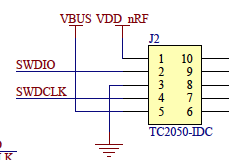
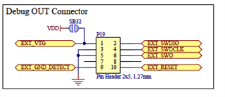
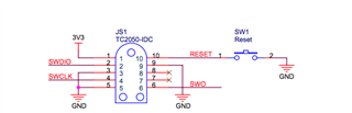
Problems-: connect TC2050-IDC-NL-050-ALL (header P19) to Dongle and either of the above DK's.  The Dongle is not Seen/Recognised by the DK's. nrf Connect only sees the the actual DK (no bootloader visible/ NRF 52 DK reports 52832 not 52840, so i know it's not seeing the dongle).

I've supplied power to the Dongle both via a usb power unit and also tried providing power through P19  (tried both bridged and cut SB47) . 

In contrast, i also have a Fanstel BT840-Dongle. Connecting this with the TC2050 in the above manor works fine. I am able to see the BT840-dongle and program both through nRF Connect and directly through SES (using the DK's above). This rules out the TC2050  as a possible issue, and gives me a reference for nRF connect / SES. 

So the question is What am i missing?

I've read the nRf52840 Programming Tutorial, but unfortunately all the links in that document are now invalid. I'm suspecting this is possible a power issue, and perhaps needing to set the REGOUT0 to 3.3V. Can i use nrfjprog  to write to the UICR register directly, if so what is the address and values i should use?        

Thanks

Revisions:- 

PCA10059 1.0.0 2019.12

PCA10056 1.0.0 2018.33

PCA10040 1.2.1 2017.22

SDK 15.3 

nrf Connect 2.6.2 for OSX

nrfjprog 9.8.1

Parents
  • Hi,

    I've read the nRf52840 Programming Tutorial, but unfortunately all the links in that document are now invalid. I'm suspecting this is possible a power issue, and perhaps needing to set the REGOUT0 to 3.3V. Can i use nrfjprog  to write to the UICR register directly, if so what is the address and values i should use?      

    Yes, this is likely the problem. You have probably erased the UICR, and not programmed it again with the correct regulator settings. In that case the nRF52840 dongle will be supplied by 1.8V, which does not match the ~3 V of the DK. I recommend you follow the suggested procedure in the Recover after an accidental UICR erase section in the end of the nRF52840 Dongle Programming Tutorial (using this link to External regulated source).

  • Hi Einer,

    Thanks for the reply,

     I don't believe i erased the UICR, I've not had to re-flash the boot loader and nRF connect is showing it is still there.  In any event, I followed the section on  Adapting firmware to set REGOUT0 properly, copied the code shown in the tutorial to the ble_app_blinky sample code, and call it before log_init(). I flashed this new ble_app_blinky along with the softDevice (s140_nrf52_6.1.1_softdevice) using nrf Connect.

    I am able to connect using the  nrf_blinky app for iphone, and yet i am still not able to debug using DK. 

    So, this leads me to believe it is something else. I've looked at the schematics for the TC5020 connector on the Dongle (J2),

    and the Debug out port on the DK (P19) 

    and noticed pin 5 on the dongle leads to VBUS whereas pin 5 on the DK Debug port leads to GND. Now, here is the interesting part, it appears that there are a couple of versions of the  TC2050-IDC, the one i have, as mentioned above is the -ALL version, which connects all the pins, the alternative version, doesn't connect pin 5 and pin 9. Below is the schematic for the TC2050 pad as implemented on the BT840 dongle i mentioned above (JS1):-

    here we can see that pin 5 also leads to GND. I suspect this is why i am not having issues with the BT840 dongle, where as I am with the nRF Dongle.

    Can you confirm this is likely the issue here?

    Also, I understand that as pin 5 and 9 are not typically connected, the dongle layout shouldn't be an issue, but can you explain what the logic is in connecting pin 5 on the dongle to VBUS?

  • Hi,

    I see. I agree that this looks strange, and seemingly they did not account for using TC2050-IDC connectors with all pins. I don't know why it is done like this on the dongle, and unfortunately I have not had a chance to check with he HW designer of the dongle why pin 5 is connected to VBUS (due to Easter holiday).

    A simple alternative could be to just solder on weirs on the plated half-holes for SWDIO and SWDCLK on the dongle, and connect to the P20 debug port on the DK. Then you also have to short the GND detect pin on the DK to GND. Alternatively soldering on a 2x5 pin header on P1 on the dongle would allow you to just hook a cable to the P19 connector on the DK, which I know is working.

Reply
  • Hi,

    I see. I agree that this looks strange, and seemingly they did not account for using TC2050-IDC connectors with all pins. I don't know why it is done like this on the dongle, and unfortunately I have not had a chance to check with he HW designer of the dongle why pin 5 is connected to VBUS (due to Easter holiday).

    A simple alternative could be to just solder on weirs on the plated half-holes for SWDIO and SWDCLK on the dongle, and connect to the P20 debug port on the DK. Then you also have to short the GND detect pin on the DK to GND. Alternatively soldering on a 2x5 pin header on P1 on the dongle would allow you to just hook a cable to the P19 connector on the DK, which I know is working.

Children
Related