This post is older than 2 years and might not be relevant anymore
More Info: Consider searching for newer posts

GPS antenna scematic for nRF9160

Hello

We are trying to finalize the layout we need for a nRF9160 module with gps capabilities.

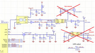
I have downloaded the schematics and layout for the devkit V0.8.5.

what we need to know is since we are only planning on using the passive gps antenna do we need the two swiches and the full network or can we just use the matching network and the passive antenna.

Also what is the purpose of disabling the passive GPS antenna ?

Parents
  • Hi Jeff,

    we are working on a new reference design, but we only have the one we have for now. 

    So the purpose of the switches in GPS-FE is to reduce LTE TX coupling GPS RX, hence avoiding LTE TX-harmonics generation by LNA at GPS front-end. Based on experience; only the series switch is needed.
    The switch in series is used as an isolating element from the external interference during LTE, but note; not during GPS RX. So the switch gives isolation, because the LTE- and GPS-antenna have isolation less than 30 dB, and this is the reason why we disables the passive GPS antenna.  

    So if you want to simply the schematic, the recommendation I can give you today is: 


    Best regards,
    Kaja

  • Adding U33, which is RF switch, increases power consumption that becomes too large to ignore. This breaks the feature of low power consumption in nRF9160. I don't want to use it.

    If you get GNSS data in one shot, not continuously, how about use EN pin of U3? When nRF9160 receives GNSS data, it enables U3 by EN pin, and when not it disables U3 by setting EN pin L. Is this approach feasible?

  • Hi Yusuke, 

    could you make a new case for your question, then it's easier for us form Nordic to follow up?

    Best regards,
    Kaja

Reply Children
Related