This post is older than 2 years and might not be relevant anymore
More Info: Consider searching for newer posts

nRF52: "spike" after last period with inverted polarity PWM

Hi,

I use the a gpiote_in_event to trigger a number of PWM pulses which works fine so far. However, the exact behaviour of the generated signal is important so that the device interfaced to the signal line does also behave correctly.

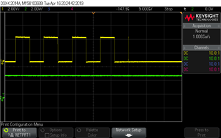
I saw that if I use inverted polarity (what is what I want to do), i get a very short pulse at the end of the PWM (after the number of specified periods). It seems that after the number of specified repetitions, the HW is just about starting another PWM sequence which is then immediately aborted.

This spike is a problem in my system, how can i get rid of it?

/EDIT: see screenshot

Parents
  • We need more information on how exactly you've implemented "gpiote_in_event to trigger a number of PWM pulses".

    Are the IN_EVENT pin or PWM pin driven high or low? 

  • Hi haakonsh,

    See the code snippet below.

    A falling edge on the HELPER_PIN should start the PWM


     //configure gpiote
     nrfx_gpiote_in_config_t helper_pin_cfg = NRFX_GPIOTE_CONFIG_IN_SENSE_HITOLO(true);
     err = nrfx_gpiote_in_init(HELPER_PIN, &helper_pin_cfg, NULL);
     nrfx_gpiote_in_event_enable(HELPER_PIN, false);
     
     
     //configure ppi channel
     uint32_t start_task_addr = nrfx_pwm_simple_playback(&m_pwm0, &seq, NBR_ADC_SAMPLES_AO, NRFX_PWM_FLAG_START_VIA_TASK|NRFX_PWM_FLAG_STOP);
     
     nrfx_ppi_channel_alloc(&ppi_ch_start_clk);
     nrfx_ppi_channel_assign(ppi_ch_start_clk, nrfx_gpiote_in_event_addr_get(HELPER_PIN), start_task_addr);
     nrfx_ppi_channel_fork_assign(ppi_ch_start_clk, nrfx_timer_task_address_get(&m_tmr1, NRF_TIMER_TASK_START));
     nrfx_ppi_channel_enable(ppi_ch_start_clk);

  • Sorry, I missed that:

    #define NBR_ADC_SAMPLES_AO  1024

    Still something missing you need to know?

  • Yeah, I need the configuration of the PWM peripheral in sdk_config.h.

    Do you mind sending me your project?

  • I could, but would need to remove some confidential stuff before, I guess.

    However, here is the PWM related passage of sdk_config.h (the legacy layer PWM stuff is commented out")

    // <e> NRFX_PWM_ENABLED - nrfx_pwm - PWM peripheral driver
    //==========================================================
    #ifndef NRFX_PWM_ENABLED
    #define NRFX_PWM_ENABLED 1
    #endif
    // <q> NRFX_PWM0_ENABLED  - Enable PWM0 instance
     
    
    #ifndef NRFX_PWM0_ENABLED
    #define NRFX_PWM0_ENABLED 1
    #endif
    
    // <o> NRFX_PWM_DEFAULT_CONFIG_OUT0_PIN - Out0 pin  <0-31> 
    
    
    #ifndef NRFX_PWM_DEFAULT_CONFIG_OUT0_PIN
    #define NRFX_PWM_DEFAULT_CONFIG_OUT0_PIN 31
    #endif
    
    // <o> NRFX_PWM_DEFAULT_CONFIG_OUT1_PIN - Out1 pin  <0-31> 
    
    
    #ifndef NRFX_PWM_DEFAULT_CONFIG_OUT1_PIN
    #define NRFX_PWM_DEFAULT_CONFIG_OUT1_PIN 31
    #endif
    
    // <o> NRFX_PWM_DEFAULT_CONFIG_OUT2_PIN - Out2 pin  <0-31> 
    
    
    #ifndef NRFX_PWM_DEFAULT_CONFIG_OUT2_PIN
    #define NRFX_PWM_DEFAULT_CONFIG_OUT2_PIN 31
    #endif
    
    // <o> NRFX_PWM_DEFAULT_CONFIG_OUT3_PIN - Out3 pin  <0-31> 
    
    
    #ifndef NRFX_PWM_DEFAULT_CONFIG_OUT3_PIN
    #define NRFX_PWM_DEFAULT_CONFIG_OUT3_PIN 31
    #endif
    
    // <o> NRFX_PWM_DEFAULT_CONFIG_BASE_CLOCK  - Base clock
     
    // <0=> 16 MHz 
    // <1=> 8 MHz 
    // <2=> 4 MHz 
    // <3=> 2 MHz 
    // <4=> 1 MHz 
    // <5=> 500 kHz 
    // <6=> 250 kHz 
    // <7=> 125 kHz 
    
    #ifndef NRFX_PWM_DEFAULT_CONFIG_BASE_CLOCK
    #define NRFX_PWM_DEFAULT_CONFIG_BASE_CLOCK 4
    #endif
    
    // <o> NRFX_PWM_DEFAULT_CONFIG_COUNT_MODE  - Count mode
     
    // <0=> Up 
    // <1=> Up and Down 
    
    #ifndef NRFX_PWM_DEFAULT_CONFIG_COUNT_MODE
    #define NRFX_PWM_DEFAULT_CONFIG_COUNT_MODE 0
    #endif
    
    // <o> NRFX_PWM_DEFAULT_CONFIG_TOP_VALUE - Top value 
    #ifndef NRFX_PWM_DEFAULT_CONFIG_TOP_VALUE
    #define NRFX_PWM_DEFAULT_CONFIG_TOP_VALUE 1000
    #endif
    
    // <o> NRFX_PWM_DEFAULT_CONFIG_LOAD_MODE  - Load mode
     
    // <0=> Common 
    // <1=> Grouped 
    // <2=> Individual 
    // <3=> Waveform 
    
    #ifndef NRFX_PWM_DEFAULT_CONFIG_LOAD_MODE
    #define NRFX_PWM_DEFAULT_CONFIG_LOAD_MODE 0
    #endif
    
    // <o> NRFX_PWM_DEFAULT_CONFIG_STEP_MODE  - Step mode
     
    // <0=> Auto 
    // <1=> Triggered 
    
    #ifndef NRFX_PWM_DEFAULT_CONFIG_STEP_MODE
    #define NRFX_PWM_DEFAULT_CONFIG_STEP_MODE 0
    #endif
    
    // <o> NRFX_PWM_DEFAULT_CONFIG_IRQ_PRIORITY  - Interrupt priority
     
    // <0=> 0 (highest) 
    // <1=> 1 
    // <2=> 2 
    // <3=> 3 
    // <4=> 4 
    // <5=> 5 
    // <6=> 6 
    // <7=> 7 
    
    #ifndef NRFX_PWM_DEFAULT_CONFIG_IRQ_PRIORITY
    #define NRFX_PWM_DEFAULT_CONFIG_IRQ_PRIORITY 6
    #endif
    
    // <e> NRFX_PWM_CONFIG_LOG_ENABLED - Enables logging in the module.
    //==========================================================
    #ifndef NRFX_PWM_CONFIG_LOG_ENABLED
    #define NRFX_PWM_CONFIG_LOG_ENABLED 0
    #endif
    // <o> NRFX_PWM_CONFIG_LOG_LEVEL  - Default Severity level
     
    // <0=> Off 
    // <1=> Error 
    // <2=> Warning 
    // <3=> Info 
    // <4=> Debug 
    
    #ifndef NRFX_PWM_CONFIG_LOG_LEVEL
    #define NRFX_PWM_CONFIG_LOG_LEVEL 3
    #endif
    
    // <o> NRFX_PWM_CONFIG_INFO_COLOR  - ANSI escape code prefix.
     
    // <0=> Default 
    // <1=> Black 
    // <2=> Red 
    // <3=> Green 
    // <4=> Yellow 
    // <5=> Blue 
    // <6=> Magenta 
    // <7=> Cyan 
    // <8=> White 
    
    #ifndef NRFX_PWM_CONFIG_INFO_COLOR
    #define NRFX_PWM_CONFIG_INFO_COLOR 0
    #endif
    
    // <o> NRFX_PWM_CONFIG_DEBUG_COLOR  - ANSI escape code prefix.
     
    // <0=> Default 
    // <1=> Black 
    // <2=> Red 
    // <3=> Green 
    // <4=> Yellow 
    // <5=> Blue 
    // <6=> Magenta 
    // <7=> Cyan 
    // <8=> White 
    
    #ifndef NRFX_PWM_CONFIG_DEBUG_COLOR
    #define NRFX_PWM_CONFIG_DEBUG_COLOR 0
    #endif
    
    // </e>
    
    // </e>

  • Hey Franz, I'm so sorry for the long delay. 

    I've tried to reproduce your issue on an internal test board, but I cannot produce the same spike. 

    I suggest you turn on high drive on the gpio via the GPIO HAL, or use:

    NRF_GPIO->PIN_CNF[31] |= (3 << 8); // High drive '0', high 'drive '1'

    Source for this issue is interference, loading of the PWM trace, poor grounding, etc.

Reply Children
No Data
Related