
I am configuring the SAADC for Single-ended mode which I would think is a simple/common task, but my output from the ADC is very jittery. It seems to jump between a good reading and (relatively) small negative values in a noise-like manner, however this is definitely not zero-mean noise. Below is a plot of what I am seeing.
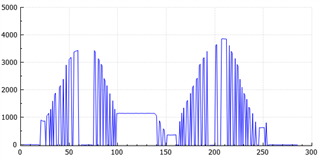
In the plot above, I am using a potentiometer to modulate the voltage. At 100 on the x-axis, I hold it constant (showing a good reading). Just after 250, I hold it constant again and the reading is wrong (it's at the small negative value).
I am using the NUS to UART example in which I have configured another nRF52832 breakout board from Sparkfun as a BLE to UART passthrough to get the data from the nRF52 DK to my computer. The data flow is as follows:
Pot -> SAADC on nRF52 DK -> NUS on nRF52 DK -> NUS on Sparkfun -> UART on sparkfun -> host computer
I have configured Timer1 and PPI channel 0 to trigger every 50 ms which in turn trigger the SAADC sample task. I am using a uin8_t data buffer which is the length of my message to the host computer. The message has the format:
<255><255><SAADCByteLow><SAADCByteHigh><\n>
Therefore the buffer is 5 bytes long. I give RESULT.PTR a pointer to the third byte in that buffer above with a MAXCNT of 1. Then when the EVENTS_END occurs, I send the buffer over NUS.
I have tried copying the buffer to a different location for sending over NUS instead of directly using the same buffer that is used in the SAADC, I have played with acquisition times, and I have tried using multiple channels (my end goal is to use 3 channels) in Scan mode. I have also tried varying the Timer1 frequency, and tried it with and without the calibration step. None of these things fix it.
My code is below for reference:
#define NUM_READINGS 1
#define MESSAGE_LENGTH (2 * NUM_READINGS + 3)
static uint16_t message_length = MESSAGE_LENGTH;
static uint8_t adc_buffer[MESSAGE_LENGTH];
static void timers_init(void) {
NRF_TIMER1->MODE = 0x0; // Select Timer Mode
NRF_TIMER1->PRESCALER = 0x4; // 1MHz (automatically will use the 1MHz clock which is lower power)
NRF_TIMER1->BITMODE = 0x2; // 24 bit timer register
NRF_TIMER1->CC[0] = 50000; // Set COMPARE0 to a value which corresponds to 50ms
NRF_TIMER1->SHORTS |= 0x1; // Cause the timer to clear everytime it reaches the value in COMPARE0
NRF_TIMER1->INTENSET |= (0x1UL << 16); // Enable the interrupt for COMPARE0
NVIC_SetPriority(TIMER1_IRQn, 6);
NVIC_EnableIRQ(TIMER1_IRQn);
}
void TIMER1_IRQHandler(void) {
uint32_t err_code;
if (NRF_TIMER1->EVENTS_COMPARE[0]) {
// Clear the interrupt
NRF_TIMER1->EVENTS_COMPARE[0] = 0;
// Wait for the ADC to be ready
while (NRF_SAADC->STATUS) { /* wait */ }
}
}
static void adc_init(void) {
NRF_P0->PIN_CNF[3] = 0x0;
NRF_P0->PIN_CNF[4] = 0x0;
NRF_P0->PIN_CNF[28] = 0x0;
// Set up PPI to make timer compare events trigger the sample task
NRF_PPI->CH[0].EEP = (uint32_t)&(NRF_TIMER1->EVENTS_COMPARE[0]);
NRF_PPI->CH[0].TEP = (uint32_t)&(NRF_SAADC->TASKS_SAMPLE);
NRF_PPI->CHENSET = (1 << 0); // Enable PPI channel 0
NRF_SAADC->INTENSET = (1 << 1); // Enable interrupt for END events
// Set the analog pins
NRF_SAADC->CH[0].PSELP = 2; // CH0 connected to AIN1 -> P0.03
// NRF_SAADC->CH[1].PSELP = 3; // CH0 connected to AIN2 -> P0.04
// NRF_SAADC->CH[2].PSELP = 5; // CH0 connected to AIN4 -> P0.28
// Set the configuration to have full VDD input range
NRF_SAADC->CH[0].CONFIG |= (2 << 8) | (1 << 12);
// NRF_SAADC->CH[1].CONFIG |= (2 << 8) | (1 << 12) | (5 << 16);
// NRF_SAADC->CH[2].CONFIG |= (2 << 8) | (1 << 12) | (5 << 16);
NRF_SAADC->RESOLUTION = 2; // 12-bit resolution
adc_buffer[0] = 255;
adc_buffer[1] = 255;
adc_buffer[message_length - 1] = '\n';
NRF_SAADC->RESULT.PTR = (uint32_t)(&adc_buffer[2]);
NRF_SAADC->RESULT.MAXCNT = NUM_READINGS;
NRF_SAADC->ENABLE = 1; // Enable the ADC
NRF_SAADC->TASKS_CALIBRATEOFFSET = 1; // Calibrate the ADC
while (!NRF_SAADC->EVENTS_CALIBRATEDONE) { /* wait for calibration */ }
NRF_SAADC->EVENTS_CALIBRATEDONE = 0;
NRF_SAADC->TASKS_START = 1; // Start the ADC
NVIC_SetPriority(SAADC_IRQn, 6);
NVIC_EnableIRQ(SAADC_IRQn);
}
void SAADC_IRQHandler(void) {
uint32_t err_code;
if (NRF_SAADC->EVENTS_END) {
// Clear the interrupt
NRF_SAADC->EVENTS_END = 0;
NRF_SAADC->EVENTS_DONE = 0;
NRF_SAADC->EVENTS_RESULTDONE = 0;
do
{
err_code = ble_nus_data_send(&m_nus, adc_buffer, &message_length, m_conn_handle);
if ((err_code != NRF_ERROR_INVALID_STATE) &&
(err_code != NRF_ERROR_RESOURCES) &&
(err_code != NRF_ERROR_NOT_FOUND))
{
APP_ERROR_CHECK(err_code);
}
} while (err_code == NRF_ERROR_RESOURCES);
NRF_SAADC->RESULT.PTR = (uint32_t)(&adc_buffer[2]);
NRF_SAADC->RESULT.MAXCNT = NUM_READINGS;
NRF_SAADC->TASKS_START = 1; // Start the ADC
}
}

