Hello,
I'm trying to test PWM with a simple example, I've edited spm via adding
KConfig:
config SPM_NRF_PWM0_NS
	bool "PWM0 is Non-Secure"
	default y
spm.c
PERIPH("NRF_PWM0", NRF_PWM0_S, CONFIG_SPM_NRF_PWM0_NS),
I'm getting the output at the boot as;
***** Booting Zephyr OS v1.13.99-ncs1-5783-g3757f8cfe6ff *****
Flash region            Domain          Permissions
00 0x00000 0x02000      Secure          rwxl
01 0x02000 0x04000      Secure          rwxl
02 0x04000 0x06000      Secure          rwxl
03 0x06000 0x08000      Secure          rwxl
04 0x08000 0x0a000      Secure          rwxl
05 0x0a000 0x0c000      Secure          rwxl
06 0x0c000 0x0e000      Secure          rwxl
07 0x0e000 0x10000      Secure          rwxl
08 0x10000 0x12000      Non-Secure      rwxl
09 0x12000 0x14000      Non-Secure      rwxl
10 0x14000 0x16000      Non-Secure      rwxl
11 0x16000 0x18000      Non-Secure      rwxl
12 0x18000 0x1a000      Non-Secure      rwxl
13 0x1a000 0x1c000      Non-Secure      rwxl
14 0x1c000 0x1e000      Non-Secure      rwxl
15 0x1e000 0x20000      Non-Secure      rwxl
16 0x20000 0x22000      Non-Secure      rwxl
17 0x22000 0x24000      Non-Secure      rwxl
18 0x24000 0x26000      Non-Secure      rwxl
19 0x26000 0x28000      Non-Secure      rwxl
20 0x28000 0x2a000      Non-Secure      rwxl
21 0x2a000 0x2c000      Non-Secure      rwxl
22 0x2c000 0x2e000      Non-Secure      rwxl
23 0x2e000 0x30000      Non-Secure      rwxl
24 0x30000 0x32000      Non-Secure      rwxl
25 0x32000 0x34000      Non-Secure      rwxl
26 0x34000 0x36000      Non-Secure      rwxl
27 0x36000 0x38000      Non-Secure      rwxl
28 0x38000 0x3a000      Non-Secure      rwxl
29 0x3a000 0x3c000      Non-Secure      rwxl
30 0x3c000 0x3e000      Non-Secure      rwxl
31 0x3e000 0x40000      Non-Secure      rwxl

SRAM region             Domain          Permissions
00 0x00000 0x01000      Secure          rwxl
01 0x01000 0x02000      Secure          rwxl
02 0x02000 0x03000      Secure          rwxl
03 0x03000 0x04000      Secure          rwxl
04 0x04000 0x05000      Secure          rwxl
05 0x05000 0x06000      Secure          rwxl
06 0x06000 0x07000      Secure          rwxl
07 0x07000 0x08000      Secure          rwxl
08 0x08000 0x09000      Non-Secure      rwxl
09 0x09000 0x0a000      Non-Secure      rwxl
10 0x0a000 0x0b000      Non-Secure      rwxl
11 0x0b000 0x0c000      Non-Secure      rwxl
12 0x0c000 0x0d000      Non-Secure      rwxl
13 0x0d000 0x0e000      Non-Secure      rwxl
14 0x0e000 0x0f000      Non-Secure      rwxl
15 0x0f000 0x10000      Non-Secure      rwxl
16 0x10000 0x11000      Non-Secure      rwxl
17 0x11000 0x12000      Non-Secure      rwxl
18 0x12000 0x13000      Non-Secure      rwxl
19 0x13000 0x14000      Non-Secure      rwxl
20 0x14000 0x15000      Non-Secure      rwxl
21 0x15000 0x16000      Non-Secure      rwxl
22 0x16000 0x17000      Non-Secure      rwxl
23 0x17000 0x18000      Non-Secure      rwxl
24 0x18000 0x19000      Non-Secure      rwxl
25 0x19000 0x1a000      Non-Secure      rwxl
26 0x1a000 0x1b000      Non-Secure      rwxl
27 0x1b000 0x1c000      Non-Secure      rwxl
28 0x1c000 0x1d000      Non-Secure      rwxl
29 0x1d000 0x1e000      Non-Secure      rwxl
30 0x1e000 0x1f000      Non-Secure      rwxl
31 0x1f000 0x20000      Non-Secure      rwxl

Peripheral              Domain          Status
00 NRF_P0               Non-Secure      OK
01 NRF_CLOCK            Non-Secure      OK
02 NRF_RTC1             Non-Secure      OK
03 NRF_NVMC             Non-Secure      OK
04 NRF_UARTE1           Non-Secure      OK
05 NRF_UARTE2           Secure          SKIP
06 NRF_IPC              Non-Secure      OK
07 NRF_VMC              Non-Secure      OK
08 NRF_FPU              Non-Secure      ERROR
09 NRF_EGU1             Non-Secure      OK
10 NRF_EGU2             Non-Secure      OK
11 NRF_TWIM2            Non-Secure      OK
12 NRF_SPIM3            Non-Secure      OK
13 NRF_TIMER0           Non-Secure      OK
14 NRF_TIMER1           Non-Secure      OK
15 NRF_TIMER2           Non-Secure      OK
16 NRF_SAADC            Non-Secure      OK
17 NRF_PWM0             Non-Secure      OK
18 NRF_GPIOTE1          Non-Secure      OK
I assume that PWM_0 initialized as Non-Secure successfully.
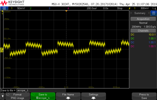
When I try the code, I don't get any error but I cannot see output on P0.2 either.
#include <nrf9160.h>
#include <zephyr.h>
#include <misc/printk.h>
#include <pwm.h>


void main(void)
{
	printk("PWM Application has started!\r\n");
        struct device *pwm_dev = device_get_binding(DT_NORDIC_NRF_PWM_0_LABEL);
        if (!pwm_dev) {
		printk("Cannot find %s!\n", DT_NORDIC_NRF_PWM_0_LABEL);
		return;
	}
        if (pwm_pin_set_usec(pwm_dev, DT_NORDIC_NRF_PWM_0_CH0_PIN, 1000, 500)) {
                printk("pwm pin set fails\n");
                return;
        }
}