This post is older than 2 years and might not be relevant anymore
More Info: Consider searching for newer posts

Hard reset during operation

I have been having issues of when I operate some components in the system the nRF52832 goes into a hard reset. I have seemed to fix a lot of the hardware issues but there is one aspect i cannot seem to eliminate and i want to confirm it will not be a long term issue. Will the nRF52832 maintain stability during operation under my use case stated below?

My system operates in advertising mode consuming around 400uA of power. When it begins to perform a task, and the current increases on the 3.3V line, the 3.3V SMPS output ramps from 3.3V to 4.2V instantaneously and then ramps down to 3.3V after 15us. 

I believe my earlier issues were with the power supply and the statement that was made on page 99 of the product specifications for the nRF52832, "A step increase in supply voltage of 300 mV or more, with rise time of 300 ms or less, within the valid supply range, may result in a system reset". I am clearly within this warning still but i seem to not be experiencing any issue with a hard reset that I was experiencing previously. Previously this rule was being violated multiple times within a certain time frame.

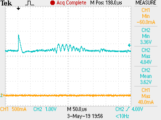
This scan is a failure which would happen 1 out of every 10 or so and cause the system to hard rest. The blue line is the 3.3V rail. Sometimes the nRF chip would not hard reset when seeing the below input. but 90% of the time when it saw this wave it would hard reset. and if it hard reset, it saw this waveform 100% of the time

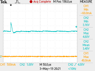
Whereas this scan is what i am seeing 100% of the time now and i do not seem to experience any hard resets during operation

Parents
  • First according to the datasheet 3.9 volts is the absolute maximum value, above which damage to the nRF52832 can be expected even if that doe not immediately show up - 4.2 volts as shown on the 'scope is far too much and is probably higher - try zooming into the peak on the 'scope before capturing the signal. "Maximum ratings are the extreme limits to which the chip can be exposed for a limited amount of time without permanently damaging it. Exposure to absolute maximum ratings for prolonged periods of time may affect the reliability of the device"

    "Operate some components .." implies that there is either a sudden significant drop in supply current on some device or there is a back-emf generated from some inductive load. In the former case perhaps a slower turn-off could be tried, in the latter a reverse-bias diode clamp. If neither of these are an option, then try isolating the nRF52832 VCC with a series R followed by a C to Gnd. A starting point would be 22R and 10uF Then compare the surge either side of the R to see if that keeps it below the magical 3.9 volt worst case on the nRF52832 side.

    A cleaner solution might be separate regulators, not required on the nRF52832 if the battery is below (say) 3.6 volts. That way current surges are isolated from the troublesome load.

  • The issue I have having is isolated to motor operation. I am using a brushed motor assembly. Every time I engage the motor i get commutator noise on the line. I have reduced the noise a significant amount but i am getting up to a 4V noise ripple that lasts 400-500ns tops. The spike lasting a fraction of that at 100-200ns tops.

    The absolute maximum rating is there a time threshold that those threshold must be sustained? Can the nRF module sustain a noise spike for let say, up to 1us before triggering a failure and resetting? or if it sees a motor noise spike within 100ns it is toast and will possibly reset?

  • This is the second issue I mention above,and the usual solution is a reversed-biased diode or zener to catch and suppress the spike. Something of an art on layout, so maybe try a few placements and see how the spike is affected. A quick search gives this link snubber discussion which gives some useful hints.

    The commutator spike is actually useful in some cases, as it indicates motor revolution without requiring an encoder, typically 6 pulses per rotation depending on commutator design.

    100nSec is sufficient to cause a problem, I would say, but I doubt that a firm specification exists. 100nSec at 4v will eventually punch a hole through some layer on the die, similar to ESD breakdown.

  • I do not have a spike or ringing that a snubber will fix. It is literally just random noise when the motor is turning. No diode or zener is going to react fast enough, i tried. There are only a few things i have not tried but it is because i am trying to modify a board. I cannot put a X2Y cap across the input and i cannot put an ferrite bead in line with the power supply due to how they routed the board. 

    I will just run thousands of cycles and we will determine if the system can survive long term shock and abuse.

    thanks

Reply
  • I do not have a spike or ringing that a snubber will fix. It is literally just random noise when the motor is turning. No diode or zener is going to react fast enough, i tried. There are only a few things i have not tried but it is because i am trying to modify a board. I cannot put a X2Y cap across the input and i cannot put an ferrite bead in line with the power supply due to how they routed the board. 

    I will just run thousands of cycles and we will determine if the system can survive long term shock and abuse.

    thanks

Children
No Data
Related