Hello,
I have some problems when running the development kit. It seems the problem might be somewhere on the PCB, something related to power sources and power distribution across the development kit.
I have programmed simple ble_app_uart program into the nRF52840 SoC. When I turn it on, the LED1 should be slowly blinking and it should be visible as a BLE device on my mobile phone. The symptoms are:
1. When I power it from the debugger USB (J2), it sometimes works and sometimes does not work. When I started working on it today, I was able to program it without problems, but the LED1 would not turn on sometimes and BLE advertising was inactive. I tried to power it off and on, program it multiple times and after about half an hour of doing stuff like that, it started working (LED1 blinks consistently and BLE is advertising). Now it works every time I power it on through the J2 USB.
2. When I try to power it from the lithium button cell, it does nothing. SW6 is set to DEFAULT and SW9 is set to VDD. The lithium cell is in good condition, it is not empty, I measured it.
3. When I try to power it from external supply, through P21, it seems to work for about one second. When i switch the SW8 power switch from OFF to ON, the LED1 blinks once and I sometimes catch a BLE advertising packet on my phone (it appears on list of devices). So it seems like it got powered on and then it powered off for some reason. I power it with 3.6V, stable DC source, had no problem with this power supply on other boards.
4. Powering it from nRF USB J3 also does not work. I switch the SW9 power source switch from VDD to USB and then connect USB to J3. Sometimes LED1 blinks for a fraction of a second. Sometimes not. BLE advertising is active also for a short time. So it is similar to powering it from external supply, but the duration for which it seems to work is even shorter.
Can you give me some tips on what to try and what parts of the developement kit to check for malfunction?
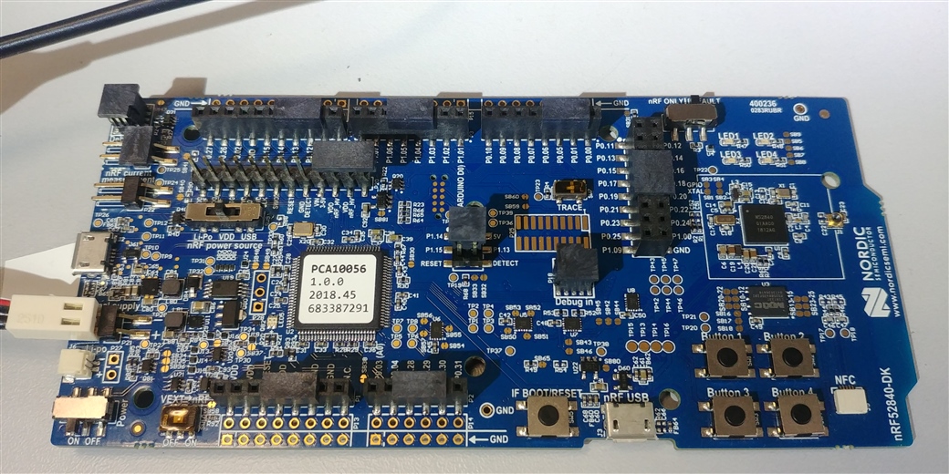
Here is a photo of my setup with external power supply. Dont worry about the colors on the connector, I couldn't fit it there the other way around. Minus is connected to the top part of the connector, plus to the bottom part.
Thanks.