
Hello ,
In this scenario, I have to measure the time interval between the START and STOP pulses generated by a peripheral device connected to nRF52 DK. The thing is START and STOP signals are passed through an OR gate to the nRF52(so, start and stop is received on a single pin). So the counter/Timer should measure between pulses START(LotoHI) and STOP(LotoHI). I tried to implement it using the pin_change_init example in which Timer0 is initialized and called from the interrupt handler function. But I could not make it work.
Appreciate if someone tech savvy could help me out in this matter.
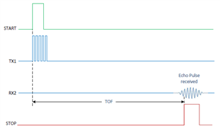
FYI Time interval range is 1.34microseconds - 38 microseconds and ref image for start and stop is attached.
Thanks
Cheers!
Updated 2019/05/17
I could get the START and STOP events working, now i am unable to capture the time interval between START and STOP pulses. Please share insights.
Program code that I tried to implement the time capture between START and STOP tasks.
Edited 2019/05/19
Removed Code from the post.
I was able to get the exact thing implemented using PPI,GPIOTE and TIMER.
This following link is useful if anybody gets to this post
https://devzone.nordicsemi.com/f/nordic-q-a/23267/how-to-measure-two-wave-delay/91489#91489

