
Hello, I have a question about using PPI with a SPI transfer.
I’m using a NRF52832 custom board with the Softdevice. I’m reading sensor data every 20ms via TWI and sampling SAADC via a PPI Channel. This data is send to an Android with NUS- nordic uart service.
So far this works perfectly.
Now I’m additionally trying to implement an SPI communication with a DAC to generate a square wave signal. So far I used a timer handle with a flag to toggle between two values. It’s a simple 24 bit transfer only which has to be done every ~25 us.
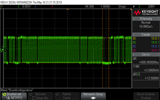
As expected once everything is running together I’m getting short delays in my square wave signal. I’m guessing because of the interrupt priorities. The DAC output signal can be seen in the oszi image below. The delays are a maximum of 300-500 us long.
This causes some issues with the device I’m trying to operate with the DAC. I thought about using PPI in combination with SPI. The problem is I'm not sure how to implement the toggling to generate a square wave signal. Additionally I need to change the transferred SPI data value every ~20 ms. For example, change the DAC output from +-1 V to +-2 V.
This is the code of my SPI-PPI module so far. Any ideas how I can toggle the SPI values and change them while everything is running? I read in this Q&A that the NRF_DRV_SPI_FLAG_TX_POSTINC flag should be used, but I don't know how to implement it.
void ppi_spi_init(void)
{

	uint8_t data[3];

	data[0] = CMD_WRITE_UPDATE_DAC_REG;
	data[1] = (input & 0xFF00) >> 8;
	data[2] = (input & 0x00FF) >> 0;


  ret_code_t err_code;

   err_code = nrf_drv_ppi_init();
   APP_ERROR_CHECK(err_code);

	/**************************************************config timer **************************************************/

		nrf_drv_timer_config_t timer_cfg = NRF_DRV_TIMER_DEFAULT_CONFIG;
		err_code = nrf_drv_timer_init(&DAC_TIMER, &timer_cfg, dac_timer_handler);

   /* setup DAC_TIMER for compare events*/
		uint32_t time_ticks =	nrf_drv_timer_us_to_ticks(&DAC_TIMER, 23);
		nrf_drv_timer_extended_compare(&DAC_TIMER, NRF_TIMER_CC_CHANNEL1, time_ticks, NRF_TIMER_SHORT_COMPARE1_CLEAR_MASK, false);
		nrf_drv_timer_enable(&DAC_TIMER);


   uint32_t timer_compare_event_addr = nrf_drv_timer_compare_event_address_get(&DAC_TIMER,NRF_TIMER_CC_CHANNEL1);


  memset(spi_rx_buf, 0, spi_length);
	spi_xfer_done = 0;

		nrf_drv_spi_xfer_desc_t xfer = NRF_DRV_SPI_XFER_TRX(data, 3, spi_rx_buf, 0);

		uint32_t flags = NRF_DRV_SPI_FLAG_HOLD_XFER           |
                 NRF_DRV_SPI_FLAG_RX_POSTINC          |
                 NRF_DRV_SPI_FLAG_NO_XFER_EVT_HANDLER |
                 NRF_DRV_SPI_FLAG_REPEATED_XFER;

		nrf_drv_spi_xfer(&spi2, &xfer, flags);

				uint32_t start_tsk_addr = nrf_drv_spi_start_task_get(&spi2);

				uint32_t end_evt_addr = nrf_drv_spi_end_event_get(&spi2);

   err_code = nrf_drv_ppi_channel_alloc(&spi_ppi_channel);
   APP_ERROR_CHECK(err_code);

   err_code = nrf_drv_ppi_channel_assign(spi_ppi_channel,timer_compare_event_addr, start_tsk_addr);
   APP_ERROR_CHECK(err_code);
}


void spi_ppi_enable(void)
{
  ret_code_t err_code = nrf_drv_ppi_channel_enable(spi_ppi_channel);

  APP_ERROR_CHECK(err_code);
}
Thank you for the help.
Best regards.
Niklas
