
Hi,
In the documentation nRF52832_v1.4, in 18.6.1 on page 82, it is indicated "A step increase in supply voltage of 300 mV or more, with rise time of 300 ms or less, within the valid supply
range, may result in a system reset", what is the valid supply voltage ? 1.7 V- 2 V?
In recommended conditions in 6 on page 20, the supply rise time (from 0 to 1.7 V) must be less than 60 ms, what happens if the rise time is much higher ?
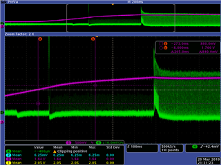
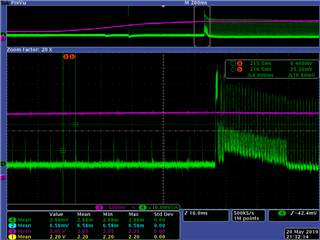
In the figure below, in green is the voltage on a 10 ohm resistance to measure the µC current consumption, in pink the supply voltage, we see that it takes 265 ms to the supply voltage to rise from 850 mV to 1.7 V. and yet the µC starts at around 1.6 V (the first current pic consumption), then we see a pic of consumption every 4 ms (that is not related to our software), when the supply voltage reaches 2V, we can see the consumption every 1ms, which proves that the CPU is already started (our software starts measurements every 1ms when Vdd reaches 2V).
So can we say that CPU can start even if the supply voltage rise time is much higher than indicated in the recommended conditions?
How can you explain the current consumption every 4 ms between the first current pic consumption and the begining of measurements every 1 ms (our software)? When did the power on rseset take place?
Thank you in advance

