This post is older than 2 years and might not be relevant anymore
More Info: Consider searching for newer posts

nRF52832: how to set AREF to external (P0.02)

Hello, 

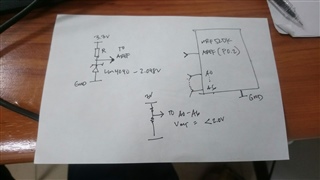
How do I set the analog reference voltage to external pin P0.02? I'm using the arduino environment so I don't know how to set it via those registers?
I'm currently using this library. 

If it is not too much, can you share to me some code which I can base my code or any reference so I can achieve this goal.

Thank you in advance.

https://github.com/sandeepmistry/arduino-nRF5

Parents
  • I'm afraid Nordic does not support arduino. Maybe some of our users can help you. 
    I suggest you submit an issue in the github repo asking for help. 

  • Thank you for the reply. I had already submitted an issue last April but maybe they are busy or pre occupied at the moment.

    Even if the code is for Segger Studio it's ok. I will try to port it to arduino since they are similar, both in C/C++. I have a little bit knowledge on this stuff but not too deep yet to write my own base on the datasheet. Although right now I'm trying to understand their nRF51822 AREF on how it works maybe I can make it as basis.  

  • Correct me if i'm wrong. I explored the datasheet of 51822 and 52832 with the base address

    0x40007000

    ADC with nRF51822
    SSADC with nRF52832

    the nRF51822 has an option of external from the CONFIG
    the nRF52832 has NO option for external on each CH[x].CONFIG / see also Figure 97: Simplified ADC block diagram of SSADC

    which I conclude that the EXTERNAL ANALOG REF is only possible with the comparator mode and not via SAADC

  • AREF: "You can use either positive or negative pin as the reference, depending on what numeric sign you want in your result. " 

    You can use any analog pin as an analog reference. I normal single-ended operation we tie the negative pin to ground, however to use an analog reference I suggest you tie the negative pin of channel 0 to AIN0 (p0.02), and the positive to whatever signal your're measuring. 

  • Here is my setup, output voltage from sensing part / lower resistor on the voltage divider varies from 0-1.8v  (6x divider like that and correction A0 - A5 only of nrf52DK). AREF voltage from LM4040-2.048V.

    So basically I just read a voltage divider circuit in each analog port.

    I'm still trying to understand your last reply. Sorry I'm still new to this nRF.

  • Your analog reference can be either; VDD/4, internal 0.6V reference (highly accurate), or you can connect your LM4040 to any analog input. 

    Your LM4040 is probably less accurate than the internal 0.6V reference, and more accurate than the VDD/4 reference. 

    What exactly are you trying to measure?

  • The LM4040 has 0.1% output tolerance so I have used it before wiith my projects with great accuracy. I need to read resistances with a 1% accuracy. What is the tolerance of 0.6v internal?

    The scenario is I have two prototypes for reading resistances but with the same voltage reading on voltmeter but different readings from the ADC of each board. So I suspect that maybe its from the analog reference so I want to use this external reference to see if it is really necessary.

Reply
  • The LM4040 has 0.1% output tolerance so I have used it before wiith my projects with great accuracy. I need to read resistances with a 1% accuracy. What is the tolerance of 0.6v internal?

    The scenario is I have two prototypes for reading resistances but with the same voltage reading on voltmeter but different readings from the ADC of each board. So I suspect that maybe its from the analog reference so I want to use this external reference to see if it is really necessary.

Children
Related