This post is older than 2 years and might not be relevant anymore
More Info: Consider searching for newer posts

nRF9160 DK UART configuration

I'm trying to understand how the UARTs are configured on the nRF9160 DK.

The spec mentions that there are two UARTs, a primary and a secondary.  https://infocenter.nordicsemi.com/topic/ug_nrf91_dk/UG/nrf91_DK/if_connector.html

And I see these being configured in the DTS file for the DK:

Fullscreen
1
2
3
4
5
6
7
8
9
10
11
12
13
14
15
16
17
18
19
20
21
uart0: uart@8000 {
compatible = "nordic,nrf-uarte";
reg = < 0x8000 0x1000 >;
interrupts = < 0x08 0x01 >;
status = "ok";
label = "UART_0";
current-speed = < 0x1c200 >;
tx-pin = < 0x1d >;
rx-pin = < 0x1c >;
rts-pin = < 0x1b >;
cts-pin = < 0x1a >;
};
uart1: uart@9000 {
compatible = "nordic,nrf-uarte";
reg = < 0x9000 0x1000 >;
interrupts = < 0x09 0x01 >;
status = "ok";
label = "UART_1";
current-speed = < 0x1c200 >;
tx-pin = < 0x01 >;
XXXXXXXXXXXXXXXXXXXXXXXXXXXXXXXXXXXXXXXXXXXXXXXXXX

So it looks like since the primary UART uses pins P0.26, P0.27, P0.28, and P0.29  and those pins are for UART0, UART0 is the primary.  UART1 is secondary.

Looking at the asset tracker application, when I look at the project configuration for the Zephyr kernel, I see that UART0 is configured for AT commands and also for Console:

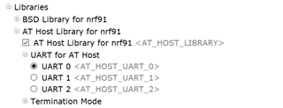
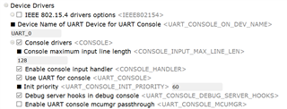
So console is UART0 and apparently it will look for AT commands there too.

But I don't see the secondary UART! configured.  Is it used for anything on the DK for the asset tracker?

Now, if I open the LTE Gateway project, it has UART2 configured as well:

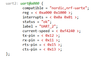
So AT_HOST and Console are still UART0, I still don't see UART1 configured, and now we have UART2.  So, with the LTE Gateway are we using the secondary UART1?  And is UART2 being used to communicate BLE data from the nRF52 to the nRF91 for this application?

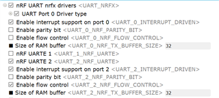
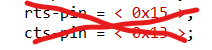
One additional question.  I see in the product spec that we can set a UART to not have hardware flow control, if I understand right.  To configure in that way, would we leave this box unchecked

and then also leave the rts and cts pins undefined in the device tree specification?

Thanks!

Erik

Parents
  • Hi Erik,

    For most of the nrf91 applications, the default software settings for UART0 and UART1 are that they are routed to VCOM0 and VCOM2 respectively. 

    The UART0 is the "primary" UART which you get the console data as well as the data from the AT host library if you have that enabled.

    The UART1 can be used for modem tracing when you have enabled the BSD_LIBRARY_TRACE_ENABLED config.

    Fullscreen
    1
    CONFIG_BSD_LIBRARY_TRACE_ENABLED=y
    XXXXXXXXXXXXXXXXXXXXXXXXXXXXXXXXXXXXXXXXXXXXXXXXXX

    That feature is used in combination with the "Trace collector" application in "nRF Connect for Desktop" as described here. 

    If you want to route UART0 or UART1 to the external pins for the nRF91 DK you can follow the instructions in this thread.

    (VCOM1 is used by the nRF52)


    The LTE Sensor Gateway Sample is programmed to use the UART2 from the nRF91 to communicate with the nRF52 to send data. 

    That's why you can see that UART2 has been enabled in that sample.


    For your last question, that should be sufficient to turn of Flow control for the chosen UART.

    Best Regards,

    Martin L.

Reply
  • Hi Erik,

    For most of the nrf91 applications, the default software settings for UART0 and UART1 are that they are routed to VCOM0 and VCOM2 respectively. 

    The UART0 is the "primary" UART which you get the console data as well as the data from the AT host library if you have that enabled.

    The UART1 can be used for modem tracing when you have enabled the BSD_LIBRARY_TRACE_ENABLED config.

    Fullscreen
    1
    CONFIG_BSD_LIBRARY_TRACE_ENABLED=y
    XXXXXXXXXXXXXXXXXXXXXXXXXXXXXXXXXXXXXXXXXXXXXXXXXX

    That feature is used in combination with the "Trace collector" application in "nRF Connect for Desktop" as described here. 

    If you want to route UART0 or UART1 to the external pins for the nRF91 DK you can follow the instructions in this thread.

    (VCOM1 is used by the nRF52)


    The LTE Sensor Gateway Sample is programmed to use the UART2 from the nRF91 to communicate with the nRF52 to send data. 

    That's why you can see that UART2 has been enabled in that sample.


    For your last question, that should be sufficient to turn of Flow control for the chosen UART.

    Best Regards,

    Martin L.

Children
No Data