This post is older than 2 years and might not be relevant anymore
More Info: Consider searching for newer posts

GPS Antenna Circuit

Hi,

we are progress of designing custom board using nRF9160.

By reading nRF documentation, my understanding is GPS circuit in Dev kit is unstable/nonperforming.

Could you please share new/updated GPS antenna section schematic.

Also please suggest smd small size ceramic antenna for Cellular-RF.

Thanks.

Parents
  • Hi,


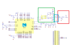
    Correct, the GPS circuitry in the current version of the DK is too complex and not performing very well. See the PS reference design for outlines of the general design. In general:

    • Green: LNA with LNA specific passives. We recommend an LNA that has the filter on the input.
    • Blue: Test connector - optional
    • Red: PCB antenna + antenna matching


    You can also use an external antenna, depending on your product requirements. If using an active antenna, you would need a bias tee on your PCB.


    You should choose a PCB antenna which has a recommended mounting that aligns well with your intended mounting. E.g. if it is recommended to be placed in the corner of a ground plane, it will not be optimal if you place it along a straight edge of the ground plane. You also need to ensure that it supports the frequency in which the bands you plan to use are placed.


    Best regards,

    Andreas 

  • Thanks for pointing to new GPS circuit and explanation.

    we do not find "QM14501"" in digikey or mouser to buy.

    Could you recommend alternative component. 

  • The Infineon BGA715N7 is what I'm going be basing our design on, it is readily available and has much higher 20dB gain, and uses less than half the current.

Reply Children
Related