This post is older than 2 years and might not be relevant anymore
More Info: Consider searching for newer posts

Custom NRF51822 board Not showing in nrfgo

Hello, I have a custom board (was built using the Nordic schematics provided with the Smart Beacon Kit). I am using J-Link LITE to try and program the board.

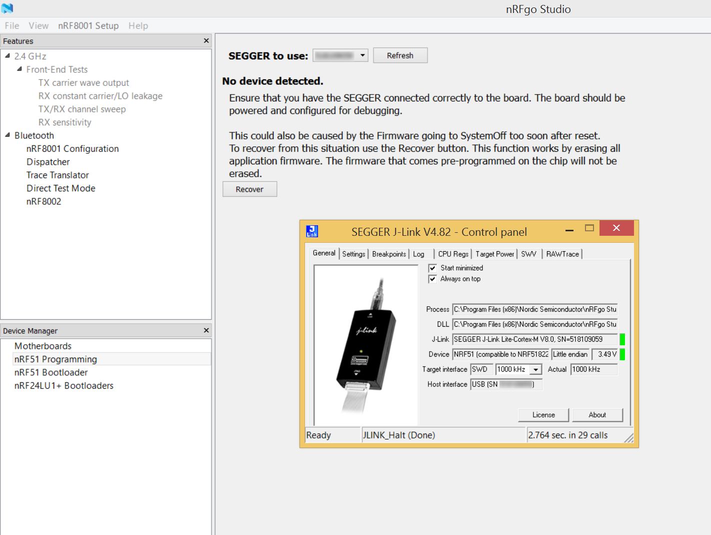
The board has power and I am able to connect the J-Link Lite. The J-Link Control Panel shows the target voltage and is "green".

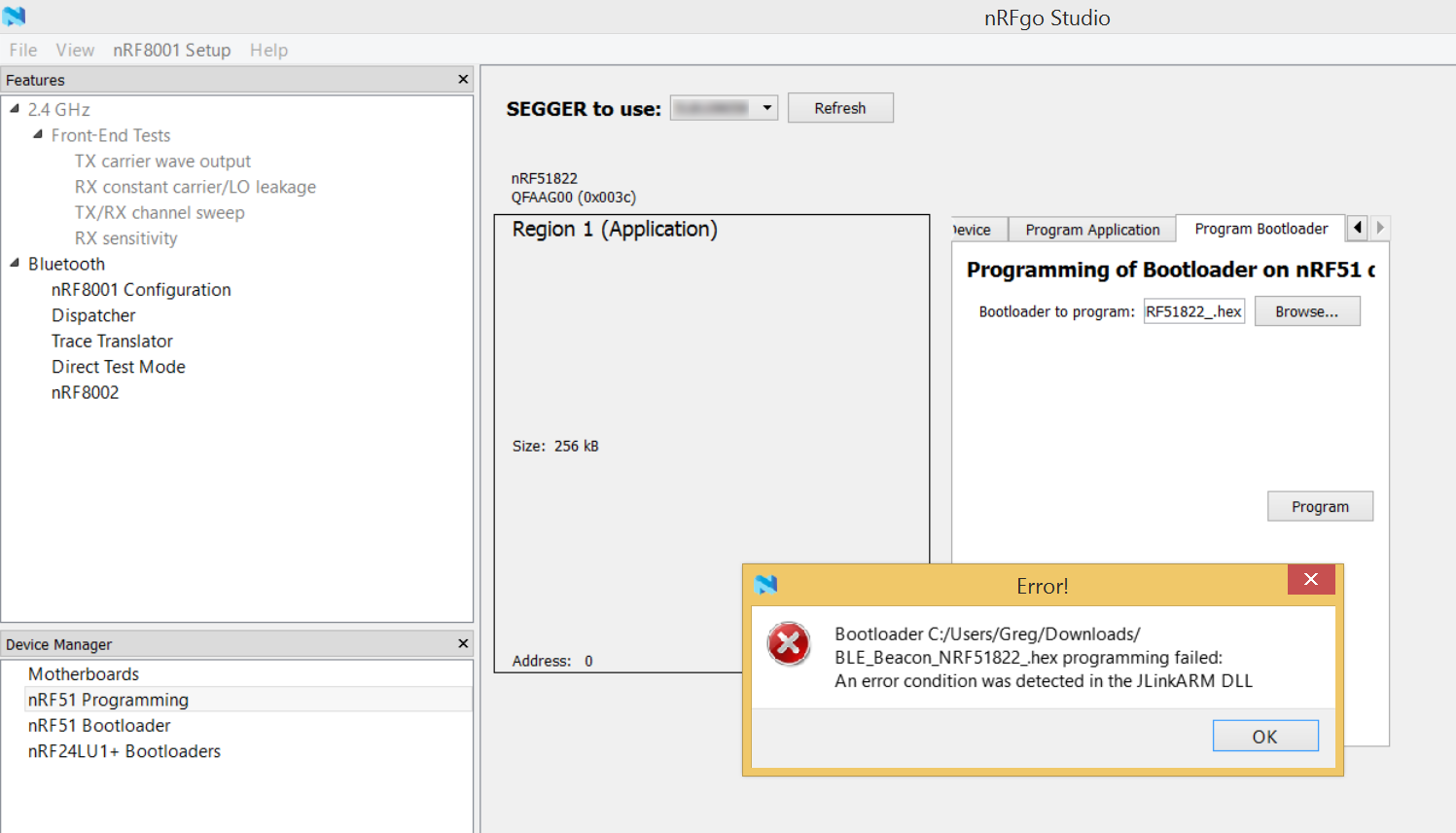
When i launch nrfgo studio to write my bootloader it just says "No Device Detected".

Again, this is a custom board with a brand new NRF51822 chip.

Please let me know if you need any more detail! Thanks!

image description

image description

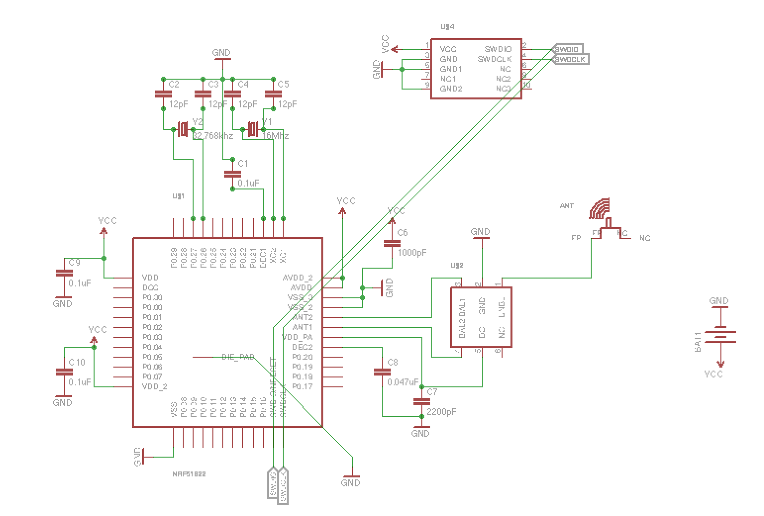
After adding the 100k Pulldown resistor to the SWDCLK. A 100k Pullup on SWDIO and corrected the 16Mhz crystal caps to 18pF (up from the shown 12pF). image description

Parents
    1. I would check to make sure that you have selected the correct load capacitor values for your crystals.
    2. Shouldn't C6 be attached to the AVDD and AVDD_2 pins? Perhaps since this pin does not have a capacitor, thus you have a odd race condition on power-up (highly highly unlikely at these capacitor values).
    3. As mentioned, make sure the J-Link can see the Vcc on the target board ( 3.0V or greater). Correct pinout
    4. How are you supplying power to the target board? Its possible the coin-cell battery has a high IR, thus the Vcc voltage pulls down below 3.0V under current consumption during start-up.
    5. Outside of these, start doing continuity checks on all you critical traces. Verify the footprint on the nRF51822 and crystals (and load caps). Finally triple check your cable connection to the target board is the correct wiring.

    Keep us posted.

Reply
    1. I would check to make sure that you have selected the correct load capacitor values for your crystals.
    2. Shouldn't C6 be attached to the AVDD and AVDD_2 pins? Perhaps since this pin does not have a capacitor, thus you have a odd race condition on power-up (highly highly unlikely at these capacitor values).
    3. As mentioned, make sure the J-Link can see the Vcc on the target board ( 3.0V or greater). Correct pinout
    4. How are you supplying power to the target board? Its possible the coin-cell battery has a high IR, thus the Vcc voltage pulls down below 3.0V under current consumption during start-up.
    5. Outside of these, start doing continuity checks on all you critical traces. Verify the footprint on the nRF51822 and crystals (and load caps). Finally triple check your cable connection to the target board is the correct wiring.

    Keep us posted.

Children
Related