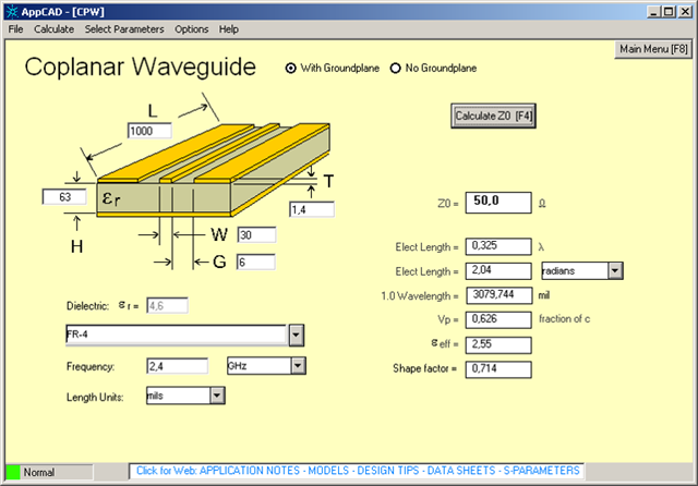
Hi, guys. I copied the EAGLE schematic and PCB drawing file from the SparkFun nRF52832 Breakout design for my custom PCB (4 layers, FR-4).
https://cdn.sparkfun.com/assets/learn_tutorials/5/4/9/sparkfun-nrf52832-breakout-schematic-v10.pdf
https://www.sparkfun.com/products/13990
However, I wanted to refer to Nordic's PCBs. Also, I'm not used to reading the PCB Gerber files.

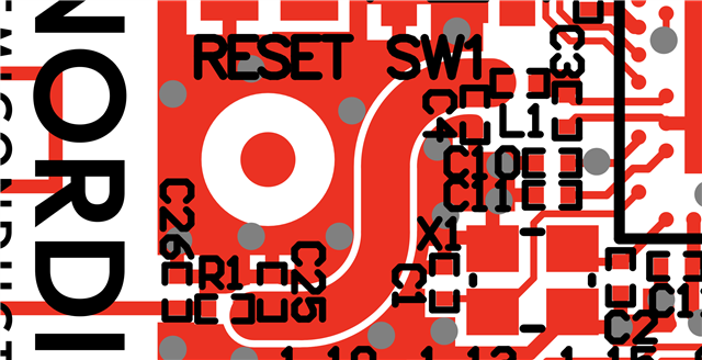
Q0. For the PCA10059 case (the nRF52840-QIAA dongle), I think this is a 2 layered board. The top copper is GND, isn't it?
Q1. For the PCA10059 case, what is connected to the bottom copper; 5V, 3.3V, GND?
Q2. For the PCA10059 case, what are the length and width of the impedance trace (L1 - C25)?
I'm surprised that the impedance trace is "curvy" because I thought this trace had to be a straight line.
Q3. For the PCA10059 case, what are the length and width of the PCB antenna trace?
Q4. What is the PCB thickness (height) of the PCA10059?
///////// Similarly

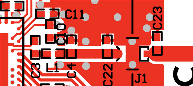
Q5. For the PCA10056 case (the nRF52840-DK 4 layered), what are each copper connected to?
Q6. For the PCA10056 case, what are the length and width of the impedance trace (C4 - C22)?
Q7. For the PCA10056 case, what are the length and width of the PCB antenna trace?
I noticed that both boards have different lengths and widths.
Also, I couldn't get a free Gerber file viewer for measuring these.
Q8. What is the PCB thickness (height) of the PCA10056?

