Hi, guys. I'm trying to create a custom 4-layered 1.6mm thick FR-4 PCB which uses the NRF52840-QIAA-R.
It's my first time using the nRF52840 so I have some questions, please.
This uses external 5V USB and there is a buck converter connected to the USB to create 3.3V.
Q0. About the VDDH (High voltage mode operating voltage, max 5.5V), I noticed that both VDD_HV and VDD_nRF (on the PCA10056) were showing the same voltage to 2.981V when SW9 is positioned to the middle.
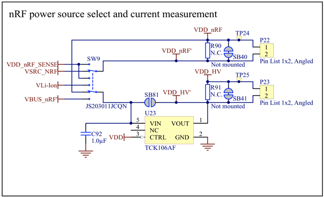
For my USB application, can I connect the buck converter's output (3.3V) to both VDDH(Y2) and VDD(W1) for using the
Normal voltage mode (pin VDD shorted to pin VDDH)?
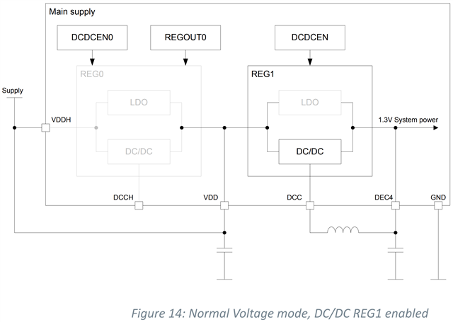
Also, if I connect both VDDH and VDD to 3.3V, I can only use DC/DC converter which can be enabled by REG1, right?
Q1. Although this application uses USB, I have to create a Li-ion powered version later. The High Voltage mode - DC/DC converter part is interesting
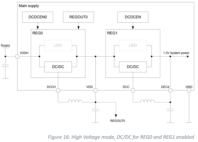
If I add the external LC filters, configure the registers for the internal DC/DC regulators, and connect the Li-ion's 3.7V or USB 5V to VDDH, does this mean that
I can remove an external buck converter? This looks like if I connect the 3.7V Li-ion to the VDDH, I don't need to provide an external 3.3V, right?
Q2. The schematic symbol,
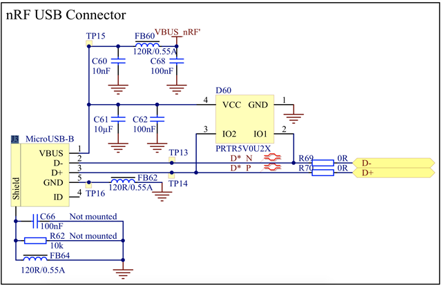
what does the red pulse, next to D* N and D* P, mean?
Q3. The USB D+, D- trace
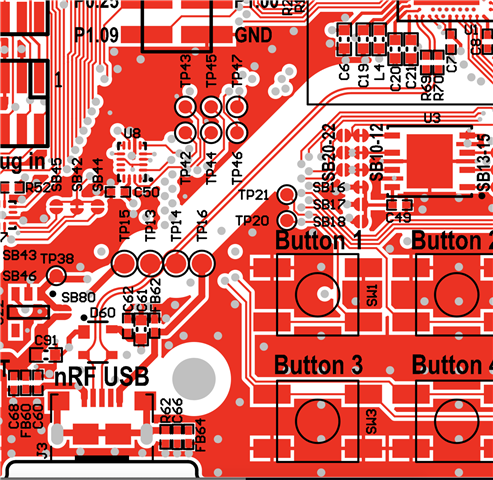
I noticed the thin line and removed copper. Are there any guidelines for drawing USB connection (D+, D- trace width/length, keep out area, etc)?
