This post is older than 2 years and might not be relevant anymore
More Info: Consider searching for newer posts

nRF52 UART connection with constant data stream capability

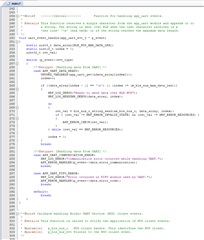
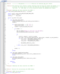
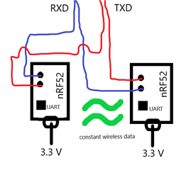
Hello, I am working on a project where I have 2 nRF52832 boards with the PCA10040. I have the example developer code examples. I am using the central and peripheral code examples to talk from one UART to another on Tera Term. Although, I noticed that this code is structured so that data is piled in an array and only sent to the other UART when I press "enter" or if it reaches a maximum size (which is very large). I am only using Tera Term to test my boards and not as part of the project. I have an external source of data that works properly on its own and am trying to use these UARTs to establish wireless communication. I have cut the solder bridges SB 22-25 to isolate PO.05 - PO.08 from nRF52832 to the Interface MCU. In pins 6 and 8 on both boards, I put TXD and RXD. Essentially what I am trying to do is have data go though the TXD & RXD wires to one UART, then wirelessly transfer data to the other UART, and have TXD & RXD wires come back. This processes will not work unless the code is structured so that data can be processed (sent & received) continuously. Or at least have it to where whatever is stacked up in the buffer is sent out every interval. I have attached the part of the code for both Central and Peripheral examples that specifically deal with data in UART. I have also put a diagram of sorts to help visualize. Any help would be great. Thanks.

Parents
  • Hi, you will get higher bandwidth when you split the data into larger chunks as opposed to sending a few bytes at a time (Note: the max data size is defined by m_nus_max_data_len), so it's probably a good idea to accumulate data at a fixed interval before transmitting as you suggested. I would probably have used a longer timer interval though. The lowest connection interval allowed by BT spec. is 7.5 ms anyway. 

    Aashay said:
    The rest of the data gets lost

     It's not lost by the Softdevice. Data passed to ble_nus_data_send() will be transmitted if the function returns NRF_SUCCESS (i.e., the link will be terminated if a packet is not received within the supervision timeout ). I think it's likely returning NRF_ERROR_RESOURCES as it's easier to fill the Softdevice's TX buffer when you send many small notifications rather than few large notifications. The message for handle value notification illustrates this: https://infocenter.nordicsemi.com/topic/com.nordic.infocenter.s132.api.v6.1.1/group___b_l_e___g_a_t_t_s___h_v_n___m_s_c.html?cp=3_4_1_1_2_4_3_5 

    I'd recommend using an app timer instance to control the data transfer. You can use the ble_app_hrs example to see how timers are initialized. 

  • Hi, I looked at the ble_app_hrs example. I am still having trouble trying to incorporate a timer instance. If I could get some assistance on what to do, it would be awesome.

  • also, i see that in tx_buffer.h that you shared. the buffer mask is set to 0x0F which is 15. I tried changing this value to see if it would work and increase the buffer size but any value other than 0F didn't work.

  • EasyDMA gives UARTE direct access to RAM without requiring the CPU. This means that you can receive data while the CPU is busy with other tasks. And you get flow control if you enable the CTS and RTS pin. 

    Try to comment this line "APP_ERROR_HANDLER(p_event->data.error_communication);" and see if it helps. It will make the app ignore "Error conditions"

  • You can't use any value for the mask.

    From tx_buffer.h

    #define TX_BUFFER_MASK                   0x0F                     //!< TX buffer mask. Must be a mask of contiguous zeroes followed by a contiguous sequence of ones: 000...111.

  • i tried using the flow control option and also commented out the APP_ERROR... so in the program i am using. i have to connect a board and then send data through. so with the 'disabled' flowcontrol i would be able to connect the boards but when sending data, errors would cause failure. with 'enabled' on the same code, i am not able to even connect my board. i dont exactly know why that is. also how would i use easyDMA or incorporate it?

  • update: so i figured out why i cant use flow control. the program i am using doesn't enable the cts and rts lines in the first place so me trying to enable them is why i was getting the error and wouldnt connect. is there any other way i could increase the how many characters or bits i can pass through the buffer at once? i tested the code with the error handler commented out on tera term and it didnt help increase how many bits i can send through the buffer at once. if i were to put "123456789123" in a .txt file. before it would just handle the error and restart the uart. but now it sends only the first 6 bits so "123456". since i cant use flow control and the error handler doesn't change my results. what other options can i use to increase how much i can pass through my buffer. also why is the buffer being limit to such a small character limit?

Reply
  • update: so i figured out why i cant use flow control. the program i am using doesn't enable the cts and rts lines in the first place so me trying to enable them is why i was getting the error and wouldnt connect. is there any other way i could increase the how many characters or bits i can pass through the buffer at once? i tested the code with the error handler commented out on tera term and it didnt help increase how many bits i can send through the buffer at once. if i were to put "123456789123" in a .txt file. before it would just handle the error and restart the uart. but now it sends only the first 6 bits so "123456". since i cant use flow control and the error handler doesn't change my results. what other options can i use to increase how much i can pass through my buffer. also why is the buffer being limit to such a small character limit?

Children
Related