Hi everyone!
I'm trying to read a register from the ADS1293 chip by using SPI but have been stuck for a good two days. The very basic code I have is right below:
#define SPI_INSTANCE   0

static uint8_t tx;
static uint8_t rx;

static const nrf_drv_spi_t m_spi_master_0 = NRF_DRV_SPI_INSTANCE(SPI_INSTANCE);

void ADS_init( void )
{
    nrf_drv_spi_config_t const spi_config =
    {
        .sck_pin        = 27,
        .mosi_pin       = 6,
        .miso_pin       = 42,
        .ss_pin         = 44,
        .irq_priority   = APP_IRQ_PRIORITY_LOW,
        .orc            = 0xFF,
        .frequency      = NRF_DRV_SPI_FREQ_4M,
        .mode           = NRF_DRV_SPI_MODE_0,
        .bit_order      = NRF_DRV_SPI_BIT_ORDER_MSB_FIRST,
    };
    ret_code_t err_code = nrf_drv_spi_init(&m_spi_master_0, &spi_config, NULL, NULL);
    //SEGGER_RTT_printf(0, nrf_strerror_get(err_code));

}

uint8_t Read_reg(uint8_t addr)
{
  tx = ADS1293_READ_BIT | addr;
  ret_code_t err_code = nrf_drv_spi_transfer(&m_spi_master_0, &tx, 1, &rx, 1);
  SEGGER_RTT_printf(0, nrf_strerror_get(err_code));
  return rx;
}
There are two things I'm not 100% sure about:
1) If the pins I'm using are correct. Is there any way to make sure that the pins I'm using are correct that is simpler than managing to read the register on the ADS? Here's how they are connected:
NRF ADS
P0.19 -> SDO
P0.20 -> SDI
P0.04 -> SCLK
P0.03 -> CSB
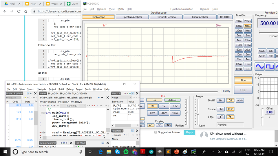
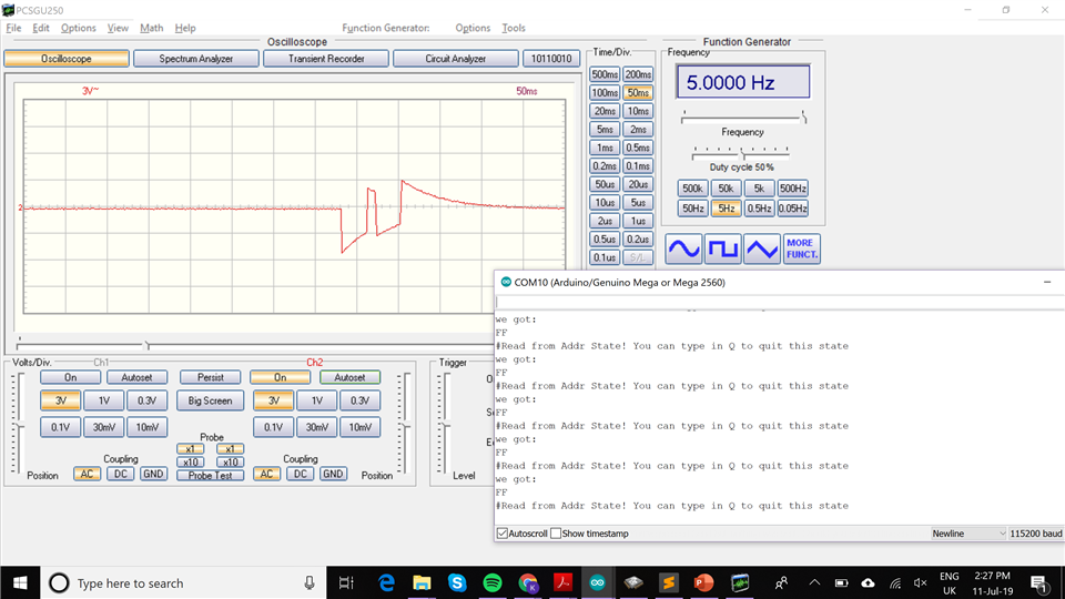
2) If the way I'm using nrf_drv_spi_transfer is correct for the ADS. If I understand correctly what's on page 37 in their documentation I should send in 8 bits and will receive 8 bits and I do this by sending in the uint8_t tx (address but set the first bit to 1) and uint8_t rx.
When I do this I get the NRF_SUCCESS code but the data received is 0x00 and is supposed to be 0x02 for the register I'm trying. I'm really new to this so I have really no idea what I should be doing right now.