Hi.
I'm using
- An nRF52832 DK
- SDK 15.3.0
- Segger IDE
- The soft device is S112
- JLinkRTTViewer for debug
- I'm using the ble_app_proximity as my starting point and have included within it the following example from github.com/.../main.c
The action I am trying to get going is to send the BLE chip to system_off() when a physical switch, connected to PIN 21, is opened. Low -> High
I then want to use a GPIOTE PORT event to wake up the device when the physical switch is closed (HIGH -> LOW). I want to use a PORT event as this is extremely low frequency changes on the physical switch, once or twice a day, so I do not need the high accuracy and high current solution. The github example above uses button presses on two different GPIO channels so I have modified the code to look at the same PIN.
He issue is I cannot get it to wakeup. Any advice on what I may be missing would be appreciated.
#define SWITCH_PIN   21
#define PIN_OUT             BSP_LED_3

/**
 * @brief Interrupt handler for wakeup pins
 */

void in_pin_handler(nrf_drv_gpiote_pin_t pin, nrf_gpiote_polarity_t action)
{
		ret_code_t err_code;

		if (pin == SWITCH_PIN)
		{
				//Turn off LED to indicate the nRF5x is in System-off mode
                NRF_LOG_INFO("Turn off LED to indicate the nRF5x is in System-off mode");
				nrf_drv_gpiote_out_set(PIN_OUT);

				//Disable power-down button to prevent System-off wakeup
                NRF_LOG_INFO("Disable power-down button to prevent System-off wakeup");
				nrf_drv_gpiote_in_uninit(SWITCH_PIN);
                nrf_drv_gpiote_in_event_disable(SWITCH_PIN);

				//Configure wake-up button
                NRF_LOG_INFO("Configure switch to wake-up");
				nrf_drv_gpiote_in_config_t in_config = GPIOTE_CONFIG_IN_SENSE_HITOLO(false);     //Configure to generate interrupt and wakeup on pin signal low. "false" means that gpiote will use the PORT event, which is low power, i.e. does not add any noticable current consumption (<<1uA). Setting this to "true" will make the gpiote module use GPIOTE->IN events which add ~8uA for nRF52 and ~1mA for nRF51.
				in_config.pull = NRF_GPIO_PIN_PULLUP;                                           										 //Configure pullup for input pin to prevent it from floting. Pin is pulled down when button is pressed on nRF5x-DK boards, see figure two in http://infocenter.nordicsemi.com/topic/com.nordic.infocenter.nrf52/dita/nrf52/development/dev_kit_v1.1.0/hw_btns_leds.html?cp=2_0_0_1_4
				err_code = nrf_drv_gpiote_in_init(SWITCH_PIN, &in_config, NULL);            					 //Initialize the wake-up pin
				APP_ERROR_CHECK(err_code);                                                      											//Check error code returned
				nrf_drv_gpiote_in_event_enable(SWITCH_PIN, true);                            								//Enable event and interrupt for the wakeup pin

				//Enter System-off
                NRF_LOG_INFO("Enter System-off");
				NRF_POWER->SYSTEMOFF = 1;
                                while(1){
								//This has been put in here to  prevent spurious calls whilst in debug mode
                                }
		}
}

/**
 * @brief Function for configuring: SWITCH_PINpin (BUTTON_1) to enter System-off,
 * SWITCH_PIN pin (BUTTON_2) to wake up from System-off, and PIN_OUT pin for LED_1 output
 */

static void gpio_init(void)
{
    ret_code_t err_code;

	//Initialize gpiote module
    NRF_LOG_INFO("Initialize gpiote module");
    err_code = nrf_drv_gpiote_init();
    APP_ERROR_CHECK(err_code);

	//Initialize output pin
    NRF_LOG_INFO("Turn on LED 4");
    nrf_drv_gpiote_out_config_t out_config = GPIOTE_CONFIG_OUT_SIMPLE(false);        	//Configure output button
    err_code = nrf_drv_gpiote_out_init(PIN_OUT, &out_config);                        						//Initialize output button
    APP_ERROR_CHECK(err_code);                                                     										  	//Check potential error
    nrf_drv_gpiote_out_clear(PIN_OUT);                                               										//Turn on LED to indicate that nRF5x is not in System-off mode

	//Configure sense input pin to enable wakeup and interrupt on button press.
    NRF_LOG_INFO("Configure sense input pin to commence shutdown procedure  on opening of the switch");
    nrf_drv_gpiote_in_config_t in_config = GPIOTE_CONFIG_IN_SENSE_LOTOHI(false);        //Configure to generate interrupt and go to system_off on pin signal high. "false" means that gpiote will use the PORT event, which is low power, i.e. does not add any noticable current consumption (<<1uA). Setting this to "true" will make the gpiote module use GPIOTE->IN events which add ~8uA for nRF52 and ~1mA for nRF51.
    in_config.pull = NRF_GPIO_PIN_PULLDOWN;                                             								//Configure pullup for input pin to prevent it from floting. Pin is pulled down when button is pressed on nRF5x-DK boards, see figure two in http://infocenter.nordicsemi.com/topic/com.nordic.infocenter.nrf52/dita/nrf52/development/dev_kit_v1.1.0/hw_btns_leds.html?cp=2_0_0_1_4
    err_code = nrf_drv_gpiote_in_init(SWITCH_PIN, &in_config, in_pin_handler);  				//Initialize the pin with interrupt handler in_pin_handler
    APP_ERROR_CHECK(err_code);                                                          											//Check potential error
    nrf_drv_gpiote_in_event_enable(SWITCH_PIN, true);                            									//Enable event and interrupt for the wakeup pin
}


/**@brief Function for application main entry.
 */
int main(void)
{
    /**bool erase_bonds;
    // Initialize.
    */
    log_init();
    NRF_LOG_INFO("Log Initialised.");
    NRF_LOG_INFO("Switch example started.");

    gpio_init();

    while (true)
    {
				//Enter System-on idle mode
				//__WFE();
				//__SEV();
				//__WFE();
				NRF_LOG_INFO("Do stuff here.");
				nrf_delay_ms(5000);
    }
}
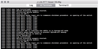
the JLinkRTTViewer log is here

Any assistance appreciated


