This post is older than 2 years and might not be relevant anymore
More Info: Consider searching for newer posts

Optimizing PCB space with footprint size

Hi,

looking to nRF52832 reference PCB designs I've noticed that BOM contains different element sizes for different packages. Such, most of capacitors for QFN48 have 0402 footprint, when WLCSP suggests 0201. The same for crystals. So I'm thinking about saving some space with smaller packages.

It's reasonable to avoid extra work recalculating the matching network and keep it intact. Also, replacing the 32MHz crystal (which itself is of the same footprint) capacitors won't really change anything:
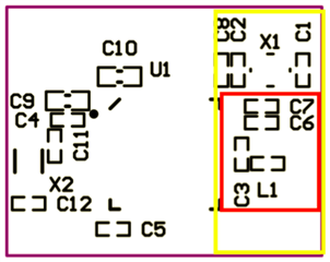
But how about other elements? Would it be safe to follow WLCSP BOM as a packaging guideline?

Also, for my understanding moving them won't affect RF performance, right?

Thanks!

Parents
  • Hi there,

    It's a little tricky to decipher what you've written, but in regards to RF performance, moving things around shouldn't affect RF performance appreciably.   If however your space saving exercise is with a view to ultimately shrink the overall board size - and hence the ground plane size - this will most certainly affect the RF performance.  Furthermore, the antenna trace will have been designed to exhibit a characteristic impedance at 2.4 GHz so pay attention to dielectric thickness, trace clearances, and physical continuity of the ground plane (and potentially omission of signal and power traces depending on how the board is stacked up) under the antenna trace.

    Whilst changes to the board means that the existing pi network will (almost certainly) be sub-optimal, how much so could vary and it may still work.  The safest bet in my view is to do your best to recreate the physical parameters relating to the antenna design of the existing antenna, test it in real life, and if the performance is not fit for purpose, you will most likely need to re-tune if the antenna.

    Good luck!

    Cheers,
    Z

  • Hi and thanks for the prompt reply!

    No, I'm not going to reduce board size - it's rather attempt to place my all other elements within my PCB constraints (roughly 17x28mm). Such, switching from 0402 to 0201 for C4, C5, C11, and C12, also to 0402 for C10, as well as employing 2012 package for X2 would save me some square mils for other components. At the same time I'm going to keep the reference design (including vias) for the yellow zone (please see my picture above).

    I understand that for the sake of simplicity the reference design tries to optimize the BOM too. So it it sounds like moving and sizing other components should not be an issue, I'll go for the experiment. Will keep you updated.

    By the way, the product specification says nothing about PCB thickness. What's the recommended value?

  • No problem.

    It's not so much a recommended value, rather what parameters the board has been designed against.  If you download the design files (Altium, Eagle etc.) and inspect the board stack-up, you should be able to glean what's on what layer, the thickness of dielectric, assumed dielectric constant etc.  Typically also prudent to get the board house to send you the datasheet for their FR4, just in case the dielectric constant is wildly different (rare, admittedly).  For your own peace of mind, once you have done your stackup and got the board house's data, it's also fairly easy to verify (or design for that matter) using AppCAD.

    If you don't mind paying a bit extra (usually varies between $50-$100), you can get your board house to impedance control the trace for you which involves a bit of trial and error on their part.  You can read a bit more about impedance control HERE.

    Cheers,
    Z

Reply
  • No problem.

    It's not so much a recommended value, rather what parameters the board has been designed against.  If you download the design files (Altium, Eagle etc.) and inspect the board stack-up, you should be able to glean what's on what layer, the thickness of dielectric, assumed dielectric constant etc.  Typically also prudent to get the board house to send you the datasheet for their FR4, just in case the dielectric constant is wildly different (rare, admittedly).  For your own peace of mind, once you have done your stackup and got the board house's data, it's also fairly easy to verify (or design for that matter) using AppCAD.

    If you don't mind paying a bit extra (usually varies between $50-$100), you can get your board house to impedance control the trace for you which involves a bit of trial and error on their part.  You can read a bit more about impedance control HERE.

    Cheers,
    Z

Children
Related