This post is older than 2 years and might not be relevant anymore
More Info: Consider searching for newer posts

HFCLK Useage

SDK 15.3 API S132

How can i implement the HFCLK using softdevice or how can i enabled it

I need to be able to run an SK6812 which has the following timing requirements
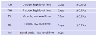
using the LFCLK and 32MHZ crystal does not do it fast enough.  I tried to make an nrf_delay_fast in which I removed a bunch of NOP lines to try and reduce the delay.

This is not fast enough. How can I implement a faster clock using softdevice 132. I was able to get this timing cycle on sdk 12.1, but i was also able to change clock sources in firmware easily in 12.1 and not so easily in 15.0. Below is how I used it in SDK 12 and then i just set the clock to that. But even if i go into the nrf_sdh.c file and change the values to these it does not work like before.

#define NRF_CLOCK_LFCLKSRC_TLBX     {   .source        = CLOCK_HFCLKSTAT_SRC_RC, \
                                        .rc_ctiv       = 16,                     \
                                        .rc_temp_ctiv  = 2,                     \
                                        .xtal_accuracy =                        \
                                            NRF_CLOCK_LF_XTAL_ACCURACY_250_PPM   }

or if it is not possible with softdevice how would you recommend I am able to get this timing sequence? 

Basically I would like to operate using the LFCLK source but when i need to turn on the LED, have the function turn on the HFCLK source and output using the HFCLK source so i can get the timing needed, then turn the HFCLK source off or maybe run a timer off the HFCLK source that triggers every 100ns and then use a counter or whatever based on t_on and t_off needs

I have been reading on PPI usage and came acrooss this

https://devzone.nordicsemi.com/f/nordic-q-a/44889/toggle-gpio-certain-number-of-times-with-ppi

i can now do a 0.3us pulse a 0.6us pulse and a 0.9us pulse.Unfortunately i cant seem to change this out once i turn it on. Is there a way to change the timer interrupt time

void adsclk_handler(nrf_timer_event_t event_type, void * p_context){
    if(toggle){
        //change the counter 
    }else{
        [CHANGE CC COUNTER]     
    }

    toggle = !toggle;

}

static void ppi_init(void)
{
    uint32_t err_code = NRF_SUCCESS;
    uint32_t compare_evt_addr;
    uint32_t gpiote_task_addr;

    toggle = false;

    if (!nrfx_gpiote_is_init())
    {
        err_code = nrfx_gpiote_init();
        APP_ERROR_CHECK(err_code);
    }

    nrfx_timer_config_t timer_cfg = NRFX_TIMER_DEFAULT_CONFIG;
    err_code = nrfx_timer_init(&m_timer1, &timer_cfg, adsclk_handler);
    APP_ERROR_CHECK(err_code);

    nrfx_gpiote_out_config_t config = NRFX_GPIOTE_CONFIG_OUT_TASK_TOGGLE(false);
    err_code = nrfx_gpiote_out_init(led_pin, &config);
    APP_ERROR_CHECK(err_code);

    nrfx_timer_extended_compare(&m_timer1, 
                                (nrf_timer_cc_channel_t)0, 
                                TIMER_INTERVAL, 
                                NRF_TIMER_SHORT_COMPARE0_CLEAR_MASK, 
                                true);
    
    err_code = nrfx_ppi_channel_alloc(&m_ppi_channel1);
    APP_ERROR_CHECK(err_code);

    compare_evt_addr = nrfx_timer_event_address_get(&m_timer1, NRF_TIMER_EVENT_COMPARE0);
    gpiote_task_addr = nrfx_gpiote_out_task_addr_get(led_pin);
    
    // hook up the compare event to trigger the toggle task
    err_code = nrfx_ppi_channel_assign(m_ppi_channel1, compare_evt_addr, gpiote_task_addr);
    APP_ERROR_CHECK(err_code);

    // enable the ppi channel
    err_code = nrfx_ppi_channel_enable(m_ppi_channel1);
    APP_ERROR_CHECK(err_code); 
}

void sk6812_led_test(void){
    nrfx_gpiote_out_task_enable(led_pin); // start sclk to shift data out
    nrfx_timer_enable(&m_timer1);
    
    nrf_delay_ms(200);
    
    nrfx_gpiote_out_task_disable(led_pin); 
    nrfx_timer_disable(&m_timer1);
}

Parents
  • Hi,

    Sorry for the late answer. It's summertime in Norway and half our staff on tech support is on vacation.

    So if I understood you problem correctly, yo want to generate 0.3 us, 0.6 us and 0.9 us pulses?

    You should RTC or TIMER instead of using CPU and nrf_delay_ms(). We have 6 compare registers in some of our timers. You can run a timer from 0, set first compare register to 0.3 us, next one to 0.3 + 0.6 us and etc., then use PPI + GPIOTE to set/clear GPIO on compare events.

    But I am still not sure what is it that you want to implement... Are you looking to implement something like the WS2812 protocol maybe?

    Best regards,

    Marjeris

  • i tried using the PPI + GPIOTE but i could not change the cycle time fast enoughafter each cycle

    RTC and timer interrupts are too slow. Fastest times i can get are greater than 1us.

    I am trying to implement a WS2812 protocvol exactly. The SK6812 is the newer variant of WS2812 but operates same protocol.

  • dmleone said:
    RTC and timer interrupts are too slow. Fastest times i can get are greater than 1us.

     
    RTC runs on LFCLK but TIMER runs on HFCLK. You should try using TIMER directly, then you will be able to go down to 62.5ns.

    But what exactly are you trying to implement? Is it something like the protocol described under 'Protocol' in this link? If this is the case you can also consider using PWM. There is an example for a WS2812 driver using PWM you can take a look at here.

    Best regards,

    Marjeris

  • This is exactly what i needed. That link is perfect and using the PWM is a brilliant method. I have 1 question regarding his implementation and I don't see why it is not working for me. It should, after displaying the color in my test function, after completing the sequence of the pwm enter the interrupt handler and reset pwm_sequenced_finished to true so it can display the next color. However, it does not enter the interrupt after the execution of the display function, but rather it seems to enter the interrupt handler after it completes my test function. so rather than flashing through RED, BLUE, and GREEN, it just stays RED.

    As a side note and i just thought this could be the issue. I am calling ws2812_led_test() from within a timer interrupt. so every 5 seconds i want it to cycle these colors. Is the fact i am in an interrupt preventing me from entering another interrupt? --This was the issue. I ran the function outside an interrupt and it worked as intended.

    void ws2812_led_test(void){
        int i;
        
        for(i = 0; i < LED_MATRIX_WIDTH; i++){
            drv_ws2812_pixel_draw(i, 0, 65280UL);       // RED
        }
        drv_ws2812_display();
        nrf_delay_ms(250);
    
        for(i = 0; i < LED_MATRIX_WIDTH; i++){
            drv_ws2812_pixel_draw(i, 0, 255UL);         // BLUE
        }
        drv_ws2812_display();
        nrf_delay_ms(250);
        
        for(i = 0; i < LED_MATRIX_WIDTH; i++){
            drv_ws2812_pixel_draw(i, 0, 6711680UL);     // GREEN
        }
        drv_ws2812_display();
        nrf_delay_ms(250);
    
        for(i = 0; i < LED_MATRIX_WIDTH; i++){
            drv_ws2812_pixel_draw(i, 0, 0UL);
        }
        drv_ws2812_display();
    
    }
    
    uint32_t drv_ws2812_display(void)
    {
        if(!pwm_sequencue_finished) 
        {
            return NRF_ERROR_BUSY;
        }
        convert_rgb_to_pwm_sequence();
        pwm_sequencue_finished = false;
        uint32_t err_code = nrfx_pwm_simple_playback(&m_pwm0, &pwm_sequence, 1, NRFX_PWM_FLAG_STOP);
        return err_code;
    }
    
    void pwm_handler(nrfx_pwm_evt_type_t event_type)
    {
        switch(event_type)
        {
    	case NRFX_PWM_EVT_FINISHED:
    	    pwm_sequencue_finished = true;
    	    break;
    	default:
    	    break;
        }
    }

Reply
  • This is exactly what i needed. That link is perfect and using the PWM is a brilliant method. I have 1 question regarding his implementation and I don't see why it is not working for me. It should, after displaying the color in my test function, after completing the sequence of the pwm enter the interrupt handler and reset pwm_sequenced_finished to true so it can display the next color. However, it does not enter the interrupt after the execution of the display function, but rather it seems to enter the interrupt handler after it completes my test function. so rather than flashing through RED, BLUE, and GREEN, it just stays RED.

    As a side note and i just thought this could be the issue. I am calling ws2812_led_test() from within a timer interrupt. so every 5 seconds i want it to cycle these colors. Is the fact i am in an interrupt preventing me from entering another interrupt? --This was the issue. I ran the function outside an interrupt and it worked as intended.

    void ws2812_led_test(void){
        int i;
        
        for(i = 0; i < LED_MATRIX_WIDTH; i++){
            drv_ws2812_pixel_draw(i, 0, 65280UL);       // RED
        }
        drv_ws2812_display();
        nrf_delay_ms(250);
    
        for(i = 0; i < LED_MATRIX_WIDTH; i++){
            drv_ws2812_pixel_draw(i, 0, 255UL);         // BLUE
        }
        drv_ws2812_display();
        nrf_delay_ms(250);
        
        for(i = 0; i < LED_MATRIX_WIDTH; i++){
            drv_ws2812_pixel_draw(i, 0, 6711680UL);     // GREEN
        }
        drv_ws2812_display();
        nrf_delay_ms(250);
    
        for(i = 0; i < LED_MATRIX_WIDTH; i++){
            drv_ws2812_pixel_draw(i, 0, 0UL);
        }
        drv_ws2812_display();
    
    }
    
    uint32_t drv_ws2812_display(void)
    {
        if(!pwm_sequencue_finished) 
        {
            return NRF_ERROR_BUSY;
        }
        convert_rgb_to_pwm_sequence();
        pwm_sequencue_finished = false;
        uint32_t err_code = nrfx_pwm_simple_playback(&m_pwm0, &pwm_sequence, 1, NRFX_PWM_FLAG_STOP);
        return err_code;
    }
    
    void pwm_handler(nrfx_pwm_evt_type_t event_type)
    {
        switch(event_type)
        {
    	case NRFX_PWM_EVT_FINISHED:
    	    pwm_sequencue_finished = true;
    	    break;
    	default:
    	    break;
        }
    }

Children
No Data
Related