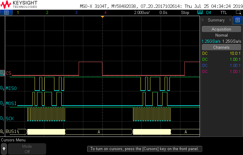
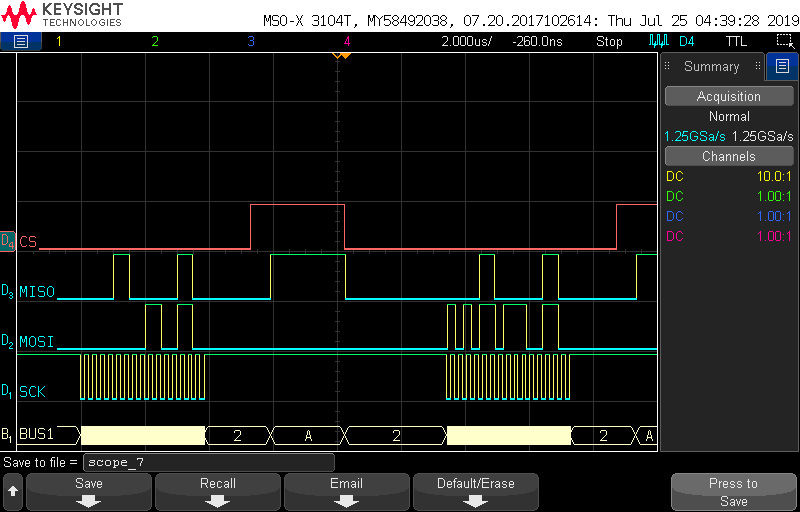
I'm attempting to write a library to allow a NRF52 DK (PCA10040) to read data from a ADXL375 accelerometer through SPI. I'm using SDK 15.0.0. I am able to read from the registers just fine, but cannot write to them. Depending on the circumstances, it will either write a persistent value to the register and then never change regardless of input; otherwise it will just not write at all.
It would be great if someone could shed some light on this. Here is the code for the read and write functions:
static const nrf_drv_spi_t * p_spi_master;
static volatile bool spi_xfer_done = true; /**< Flag used to indicate that SPI instance completed the transfer. */
static const nrf_drv_spi_config_t adxl375_spi_config =
{
.irq_priority = APP_IRQ_PRIORITY_LOW,
.orc = 0xCC,
.frequency = NRF_DRV_SPI_FREQ_4M,
.mode = NRF_DRV_SPI_MODE_3, // CPOL = 0, CPHA = 0
.bit_order = NRF_DRV_SPI_BIT_ORDER_MSB_FIRST,
.mosi_pin = SPIM1_MOSI_PIN,
.ss_pin = SPIM1_SS_PIN,
.miso_pin = SPIM1_MISO_PIN,
.sck_pin = SPIM1_SCK_PIN,
};
void adxl375_spi_srv_init(const nrf_drv_spi_t * m_spi_master)
{
p_spi_master = m_spi_master;
// Initialize the SPI instance to use with ADXL362 accelerometer
APP_ERROR_CHECK(nrf_drv_spi_init(m_spi_master, &adxl375_spi_config, NULL, NULL)); // No event handler, SPI will be in blocking mode
}
uint8_t SPItransfer(uint8_t txData)
{
uint8_t p_tx_data;
uint8_t p_rx_data;
p_tx_data = txData;
uint32_t err_code = nrf_drv_spi_transfer(p_spi_master, &p_tx_data, 1, &p_rx_data, 2);
APP_ERROR_CHECK(err_code);
return p_rx_data;
}
uint8_t oneByteRead(uint8_t address) {
uint8_t tx = (ADXL375_SPI_READ | (address & 0x3F));
uint8_t rx = 0;
nrf_gpio_pin_clear(adxl375_spi_config.ss_pin);
//Send address to read from.
SPItransfer(tx);
//Read back contents of address.
rx = SPItransfer(0x00);
while (!spi_xfer_done)
__WFE();
nrf_gpio_pin_set(adxl375_spi_config.ss_pin);
return rx;
}
void multiByteRead(int startAddress, char* buffer, int size) {
int tx = (ADXL375_SPI_READ | ADXL375_MULTI_BYTE | (startAddress & 0x3F));
nrf_gpio_pin_clear(adxl375_spi_config.ss_pin);
//Send address to start reading from.
SPItransfer(tx);
for (int i = 0; i < size; i++) {
buffer[i] = SPItransfer(0x00);
}
nrf_gpio_pin_set(adxl375_spi_config.ss_pin);
}
void oneByteWrite(uint8_t address, uint8_t data) {
int i;
int tx = (ADXL375_SPI_WRITE | (address & 0x3F));
nrf_gpio_pin_clear(adxl375_spi_config.ss_pin);
//nrf_delay_ms(10);
//Send address to write to.
SPItransfer(tx);
//Send data to write.
SPItransfer(data);
while (!spi_xfer_done)
__WFE();
nrf_gpio_pin_set(adxl375_spi_config.ss_pin);
}


