This post is older than 2 years and might not be relevant anymore
More Info: Consider searching for newer posts

I need a working NRF24L01+ + RFX2401C circuit diagram

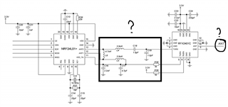
Hello, i made my own working NRF24L01+ using the reference design from the datasheet and it worked quite well. But i needed some more range so i wanted to add PA+LNA module which is RFX2401C but instead of using caps and inductors i went with a balun and band pass filter. although they replaced quite abit of components, design did not work at all. it acts as if it completely dead and i dont wanna waste any more components.

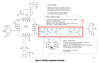
i really want to go with caps and inductors and give it a go. is there any schematic that i can work with please? thanks

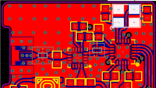
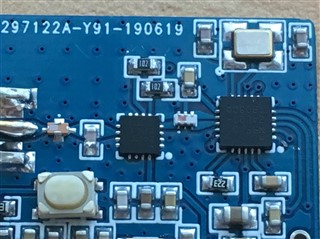
i attached the design and finished board which didnt work at all.

Parents
  • i went for hunting around the web for some ideas. so this is the reference design and particularly interested with ANT1 ANT2 and VDDPA pin connections. to my understand regardless of RFX2401C i need to populate L1,L2,L3, C3,4,5 and 6.

    then i found this design which im not sure of its source. but the first black box seems like the same as the reference design of nrf24l01+ with addition of TXEN and RXEN pins through 1k series resistor but ANT harmonic filtering is missing.

    edit:also just noticed L1,2 and 3 values are different from the reference nrf24l01 design..

    looking at the RFX2401C datasheet in the red box that i marked is the LC filter and C3,4,5,6,7 as well as L1,2 must be populated.

    do these schematics looks ok? i guess if i add the last LC filter part to second picture where ANT is marked would be ok?

Reply
  • i went for hunting around the web for some ideas. so this is the reference design and particularly interested with ANT1 ANT2 and VDDPA pin connections. to my understand regardless of RFX2401C i need to populate L1,L2,L3, C3,4,5 and 6.

    then i found this design which im not sure of its source. but the first black box seems like the same as the reference design of nrf24l01+ with addition of TXEN and RXEN pins through 1k series resistor but ANT harmonic filtering is missing.

    edit:also just noticed L1,2 and 3 values are different from the reference nrf24l01 design..

    looking at the RFX2401C datasheet in the red box that i marked is the LC filter and C3,4,5,6,7 as well as L1,2 must be populated.

    do these schematics looks ok? i guess if i add the last LC filter part to second picture where ANT is marked would be ok?

Children
No Data
Related