This post is older than 2 years and might not be relevant anymore
More Info: Consider searching for newer posts

I need a working NRF24L01+ + RFX2401C circuit diagram

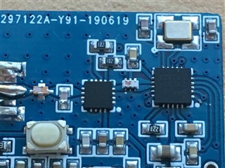
Hello, i made my own working NRF24L01+ using the reference design from the datasheet and it worked quite well. But i needed some more range so i wanted to add PA+LNA module which is RFX2401C but instead of using caps and inductors i went with a balun and band pass filter. although they replaced quite abit of components, design did not work at all. it acts as if it completely dead and i dont wanna waste any more components.

i really want to go with caps and inductors and give it a go. is there any schematic that i can work with please? thanks

i attached the design and finished board which didnt work at all.
Parents
  • reflowing the board made it work also second module worked as well so i guess there was some physical connection issue although visibly i couldnt spot a dodgy connection. 

    but im still interested in making another one without balun and a band pass filter. balun is tiny hard to see its tiny connections with bare eyes :)

Reply
  • reflowing the board made it work also second module worked as well so i guess there was some physical connection issue although visibly i couldnt spot a dodgy connection. 

    but im still interested in making another one without balun and a band pass filter. balun is tiny hard to see its tiny connections with bare eyes :)

Children
  • thanks for the share and it will work it for me.

    fmwa apk anti-ban

  • also from my simple tests i can tell that ready bought quality nrf24l01+ modules which are available in aliexpress(with genuine nrf chips) gives me exactly the same results in signal strenght. But they mostly use u.fl connector which dodgy and fragile. with custom made you are free to use any connector in my case i wont use anything other than SMA.