This post is older than 2 years and might not be relevant anymore
More Info: Consider searching for newer posts

how can I burn adafruit nRF52 Bootloader to nRF52832 chip

Hi

I have the Adafruit Feather nRF52 Bluefruit - nRF52832 board that I can program it using Arduino via Adafruit library in Arduino without any problems. 

Now I have an external nRF52832 chip and I have nRF52 DK too. I tried to program the external nRF52832 using the Adafruit library in Arduino but seems like it won't work until I burn the adafruit Bootloader to the external nRF52832 first (excuse me for not figuring this out from the beginning cause I'm a beginner in this field).

So, the question now is how can I burn the adafruit bootloader to my external nRF52832 so that I can program it using Adafruit Arduino library?

Thanks in advance!

  • Thank you so much, I followed everything that you suggested.

    1- I checked that the VTG is connected directly to the VDD of my external nRF52832 

    2- ran all the commands from the link you gave to me to burn the bootloader and it worked successfully. 

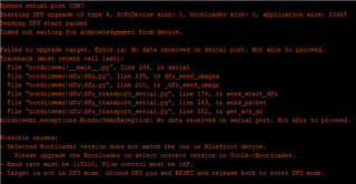
    However, after burning the bootloader to my external nRF52832, I connected my external nRF52832 to the USB port to program it using Arduino, and the code was successfully uploaded and the board was working fine. But, when I tried to upload another Arduino code to the external nRf52832, I received this error again!!

    So, does it mean that every time I need to upload a code to my external nRf52832 chip using Arduino I will then have to burn the bootloader again?!

    Cause I did burn the bootloader again and I managed to upload only one Arduino code, and when I try to upload another code I receive the same error.

  • Don't see a exposed SW interface on your schematic witch will make it impossible to burn a bootloader on a clean chip.

    I'm sorry, but I don't understand what you mean?!

  • I'm sorry, but I don't understand what you mean?!

    Was referring to the pins SWDIO and SWCLK used to program the chip. Clearly not the case since you get the chip programmed.

    I received this error again!!

    Since you can flash the chip once it tells me that it is the last point in the error log is the cause: "target is not in DFU mode"

    dfu/p0.20, are you pulling this pin low and pulling the resetting low before flashing from Arduino? This will activte the DFU mode.
    hold dfu/p0.20 low > press reset > release dfu/p0.20
    Assuming these pins are connected to buttons.

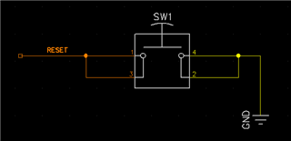
  • in my schematic design, I have the following:

    1- the DFU/P0.20 is not connected to anything. 

    2-the RESET/P.21 is connected to a switch to the ground as shown 

    I followed what you suggested, hold DFU low, pressed the reset button to the ground and released, then released the DFU and then Uploaded my code using Arduino and it worked successfully

    But why I don't have to hold the DFU and the RESET to Low when I program it the first time?

    Why do I need to do that in the second time and all the times after?

    Thank you!

  • But why I don't have to hold the DFU and the RESET to Low when I program it the first time?

    Cause there is nothing for the DFU to jump too. Think of it like having two separate applications running.

    When the chip is powered or reset. The dfu runs first. It then checks if there is another application to run or if the button presses. If the button is not press and there is a application, jump to application. So the button basically tells the DFU wait I want to flash, don't jump. 

    This method is standard practice. There are ways to get around this using CTS and DTR pins on the usb-to-serial chip.

    Also please verify the answer. 

Related