This post is older than 2 years and might not be relevant anymore
More Info: Consider searching for newer posts

External Programming of a BL651 dev board using nRF52 DK

Hi,

I have recently developed a simple custom board with the use of the BL651 module to have a dev board for myself. Although the schematic diagram is simple and the PCB does not have any issues of incorrect soldering, I was not able to detect the BL651 module over the nrf52 DK using either P20 or P19 headers.

I have already gone through most of the previous posts with issues of programming externally with the nrf52 DK and if the connections are correct between the 2 boards, but I was still not succesful in detecting the nrf52810 of the BL651.

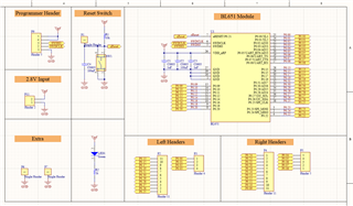
As such I checked the signals from the SWD IO and SWD CLKfrom the nrf52 DK and was not able to detect any changes in the voltage levels using an oscilloscope. For reference, here is the schematic I designed maybe there is something I missed.

Note that this is m first time using the Nordic Enviroment, where I am using the Segger EMbedded Studio for development and the nRF Connect, nRF GO Studio and the nrfjprog commands to try and detect the custom device.

Do you have any suggestion as to why I am not able to detect the BL651 IC and why does the nRF52 DK does not output any signals on the SWD IO and SWD CLK, as I have been stuck on this problem for 2 weeks as of now.

Thank you.
  • I would recommend posting the exact connections in the two cases which you tried; both to P19 and to P20. Particularly important are the Gnd and Vcc connections, and how vnrf is derived on the 2.8v input connector but we need to see all of the connections to be able to diagnose.

  • 2.8V was provided with both the nrf52 DK and also tested using an external voltage supply, using the P11 header in my schematic. 

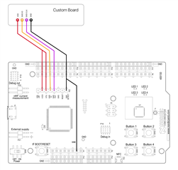
    The connection between the board with respect to the P20 of the DK was done as follows.

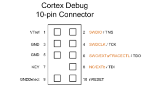
    For the P19 I had an Atmel ICE adaptor board to connect the 10-pin 1.27mm cable from which I mapped the connections and checked them through a multimeter, and the 10-pin connector (P19) was based to have the following connections for a typical Cortex JTAG/SWD Pinout. I still have to retest, but I am fairly certain the remapping is correct.


    However, with respect to the schematic in the main thread, did you find any inconsistencies in the connections for the BL651?

  • Note P19 is not the same as P20, P19 uses EXT_GND_DETECT whereas P20 uses SH_GND_DETECT. Does it matter? Who knows, they go to different pins on the SAM Segger interface but I would suggest P19 pin is the better choice as the shield Gnd detect is for things like external arduino boards. I program similar modules via a 10-pin connector from P19 without any issues. I posted some photos a long time ago in this case programming-prototype-board-from-52-dk

    I looked at the schematic, only (unlikely) issue is if the switch was a NC instead of the intended NO. Worth testing with a meter maybe. nRFGo Studio is very slow at first detection of boards sometimes (click on nRF5x Programming), and has now been replaced with nRF Connect. nRFGo is fine for initial programming and recovery from locked state however, and often a "Recover" command is required if the module is supplied locked (most are).

  • I tested the "Recover" command without any success, and I tried both the nRFGo Studio and the nRF Connect. Furthermore, as of yet I have not yet been able to retrieve the ID of the device apart from that on the nRF52 DK.

    For P19 are there any specification of the pinout for it? As I just assumed that the connector is equivalent to a Cortex Debug 10-pin connector as I have illustrated in the previous post.

  • This is what I use on target boards using modules which have both the 10-way .05" pitch connector (same as P19) and a Tag-Connect 6-pin connector:

    10-Pin Cortex Debug Connector to 6-Pin TC2030 Footprint
    =======================================================
    1 VCC Sense     1
    3 GND           5
    5 GND           5
    7 NC / RTCK     -
    9 GND Detect    5
    2 SWDIO / TMS   2
    4 SWCLK / TCK   4
    6 SWO / TDO     6
    8 NC / TDI      -
    10 nRESET       3

    The target boards have the connection from the 10-way header as described above (all of them, no missing Gnd for example). I use a simple 10-way ribbon between nRF52DK P19 and the target board header.

    The 6-pin Tag-Connect is defined as this, which also works using the 6-pin to 20-pin J-TAG adapter board::

    1 VCC
    2 SWDIO / TMS
    3 nRESET
    4 SWCLK / TCK
    5 GND (also connected to GNDDetect)
    6 SWO / TDO

    P19 description and circuit diagram are shown in the nRF52DK User Manual:

    nRF52_DK_User_Guide_v1.2.pdf

Related