Hello,
I have a fewURGENT questions.
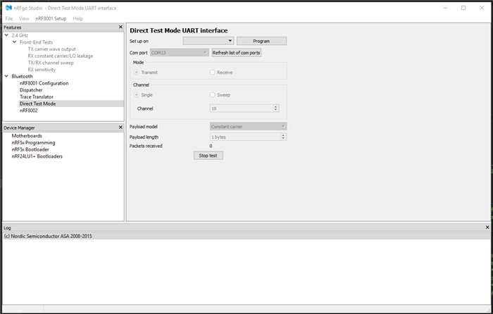
I have the NINA B112 by u-blox on a custom PCB (datasheet here). We require regulatory testing of the BLE. The NINA B112 is based on Nordic's nRF52832 Bluetooth module (info here and here); therefore, I think it would be useful for our testing facility to be able to use nRFgo Studio together with the nRF52832/NINA B112 in Direct Test Mode (DTM) (info here).
Here is some info on my setup. I have Nordic's SDK v15.3.0 (info here). Development is on a Windows10 PC. I am using a gcc based compiler; I am using the GNU Tools ARM Embedded toolchain (version 8.3.1, found here) which I point to in Makefile.windows in ...nRF5_SDK_15.3.0_59ac345\components\toolchain\gcc. I am compiling using the makefile in ...nRF5_SDK_15.3.0_59ac345\examples\dtm\direct_test_mode\myboard\blank\armgcc. My build tool is make.exe from MinGW (found here) with the path MinGW\msys\1.0\bin which I run in a command window using Git Bash (found here). I am editing the source code using Visual Studio Code and/or Notepad++. I am flashing the nRF52832 using a Segger J-Link connected to the SWDIO/SWDIO pins on the NINA B112. The UART pins are converted to RS-232 levels on the custom PCB. I am using a RS-232/USB converter to interface with the PC.
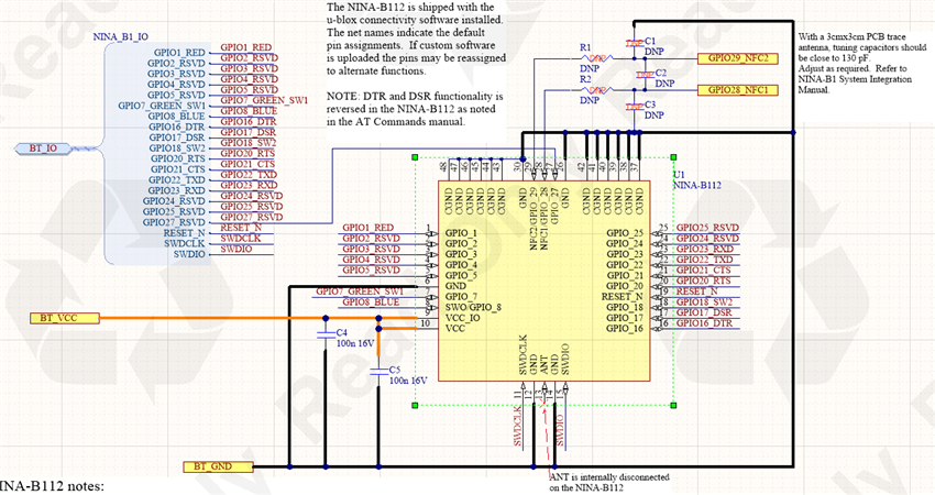
Below is the schematic of the NINA B112 on the custom PCB. For DTM, I am only interested in using the UART pins (shown as pins 20,21,22, and 23 for RTS, CTS, TXD, and RXD, respectively), and the BLE antenna, obviously (note: the antenna is integrated on the NINA B112).
I modified the pca10040.h file in ...\nRF5_SDK_15.3.0_59ac345\components\boards and renamed it myboard.h. I modified boards.h (in ...\nRF5_SDK_15.3.0_59ac345\components\boards) with the lines #elif defined(BOARD_MYBOARD) #include "myboard.h". The board file is shown below in its entirety (edit: I changed the pin numbers thanks to the response of one contributor. See comments below).
#ifndef MYBOARD_H
#define MYBOARD_H

#ifdef __cplusplus
extern "C" {
#endif

#include "nrf_gpio.h"

/* default GPIO nRF52832
#define RX_PIN_NUMBER  8
#define TX_PIN_NUMBER  6
#define CTS_PIN_NUMBER 7
#define RTS_PIN_NUMBER 5
#define HWFC           true
*/
// NINA UART GPIO pins
#define RX_PIN_NUMBER  5
#define TX_PIN_NUMBER  6
#define CTS_PIN_NUMBER 7
#define RTS_PIN_NUMBER 31
#define HWFC           false


#ifdef __cplusplus
}
#endif

#endif // MYBOARD_H
As can be seen in myboard.h, most of the functionality included on pca10040 has been removed (buttons, switches, LEDs, Arduino interfacing, etc.). We require only the UART functionality. I defined the UART pins to those shown in the schematic above, and disabled hardware flow control.
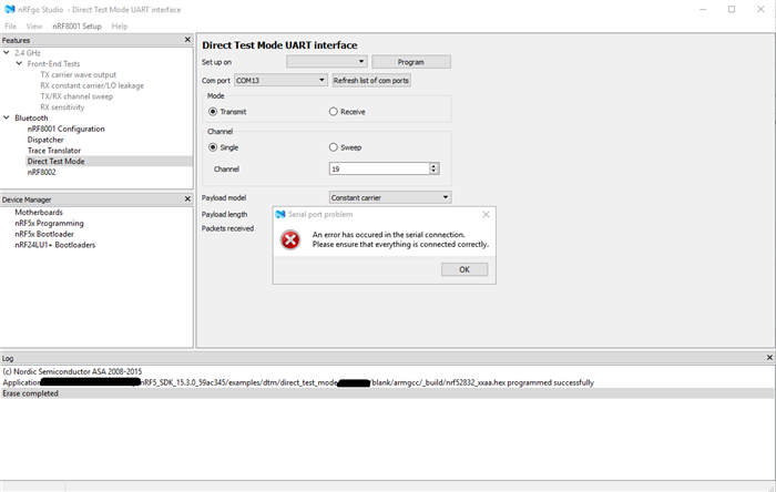
After flashing this code to the nRF52832/NINA B112, I attempt to connect to nRFgo Studio in the Direct test Mode but get the following error: "An error has occurred in the serial connection. Please ensure everything is connected correctly". See screenshot below.
I am on the correct serial port. I swapped the Tx/Rx pins and confirmed this is not the problem. When I scope the Tx/Rx RS-232 pins on our PCB, when idle the voltage levels are -5.4V and -9.5V, respectively, which is as expected. When I click the "Start Test" button in nRFgo Studio, I see the following waveform (blue trace -> Rx, yellow -> Tx). It looks like nRFgo Studio is attempting to connect to the nRF52832/NINA B112, but there is no response.
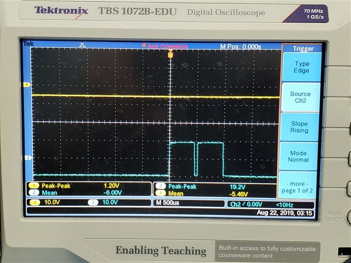
Q1 - Is the output waveform from nRFgo Studio what I should expect?
I think one potential issue is this: I don't think I have the correct UART pin numbers/names. The pin naming/numbering convention used on the NINA B112 appears to be different than on the nRF52832. The pinout of the nRF52832 is shown below for reference.
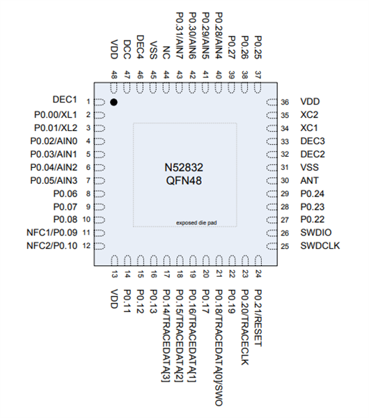
For example, the antenna pin is pin 30 on the nRF52832 but is pin 13 on the NINA B112. Further, the SWDIO/SWDCLK pins are pins 26/25 on the nRF52832 but are pins 15/11 on the NINA B112. The default UART pins are 5,6,7, and 8 on the nRF52832, but we are physically connected to pins 20,21,22,ans 23. I know the GPIO pins can be remapped to UART pins on the nRF52832, but I am not sure how the nRF52832 pins connect to those on the NINA B112.
Q2 - Can anyone help me determine the correct UART pin numbers for this application? (edit: I think I have the correct pin numbers now, thanks to one of the comments below, but I still get the same error in nRfgo Studio).
It doesn't look like there are any other changes that need to be made in the source code. The main.c source code (found in ...nRF5_SDK_15.3.0_59ac345\examples\dtm\direct_test_mode) includes a function call to uart_init() which is shown below.
/**@brief Function for UART initialization.
 */
static void uart_init(void)
{
    uint32_t err_code;
    const app_uart_comm_params_t comm_params =
      {
          RX_PIN_NUMBER,
          TX_PIN_NUMBER,
          RTS_PIN_NUMBER,
          CTS_PIN_NUMBER,
          APP_UART_FLOW_CONTROL_DISABLED,
          false,
          DTM_BITRATE
      };

    APP_UART_FIFO_INIT(&comm_params,
                       UART_RX_BUF_SIZE,
                       UART_TX_BUF_SIZE,
                       uart_error_handle,
                       APP_IRQ_PRIORITY_LOWEST,
                       err_code);

    APP_ERROR_CHECK(err_code);
}
The struct app_uart_comm_params_t is defined in app_uart.h (found in ...\nRF5_SDK_15.3.0_59ac345\components\libraries\uart) and is shown below.
/**@brief UART communication structure holding configuration settings for the peripheral.
 */
typedef struct
{
    uint32_t                rx_pin_no;    /**< RX pin number. */
    uint32_t                tx_pin_no;    /**< TX pin number. */
    uint32_t                rts_pin_no;   /**< RTS pin number, only used if flow control is enabled. */
    uint32_t                cts_pin_no;   /**< CTS pin number, only used if flow control is enabled. */
    app_uart_flow_control_t flow_control; /**< Flow control setting, if flow control is used, the system will use low power UART mode, based on CTS signal. */
    bool                    use_parity;   /**< Even parity if TRUE, no parity if FALSE. */
    uint32_t                baud_rate;    /**< Baud rate configuration. */
} app_uart_comm_params_t;
From the above two code snippets, it looks like comm_params.rx_pin_no = RX_PIN_NUMBER, etc., which should match the definitions in myboard.h. It doesn't look like there are any other changes that need to be made.
Q3 - Are there any other modifications that need to be made in the source code?
Thank you.
Mark


