This post is older than 2 years and might not be relevant anymore
More Info: Consider searching for newer posts

Using transistor with GPIO to switch another chip

Hello

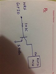
I am using pin 1.15 of nrf52840 dongle with transistor with enable pin of another chip. The other chip is a wifi chip which I only want to switch on whenever I have data to send to that chip.

My software design is like this, switch on the chip, send the data and switch off the chip.

I have used a transistor circuit whose base pin when connected to high (3.3V), switches on the wifi chip and when connects to low (0V) switches it off. But when I try to do the same with the dongle, it is not working. The dongle is not able to supply 3.3V when connected to the transistor circuit, and when I disconnect the circuit, it supllies 3.3V. This may be related to current but I am using 10K base resistor. I am attached the picture for your reference.

I appreciate your suggestions.

Regards,
Parents
  • AFAIK esp32 board has an internall pull-up on EN pin (oops.. we don't know what board you have..)

    I can see two cases:

    - your esp32 board is not powered at all, and it tries to get parasite power from EN pin

    - your board is held in reset by internal cirquitry (DTR=1 RTS=0 causes that)

  • I want to use nrf gpio to switch esp32 on and off. How can I achieve this. I connected gpio with transistor to drive esp32 enable pin high and low but could not achieve anything. Plus there is another issue that is related to this, that when my esp32 is off, the nrf dongle does not work either, I donot know why?

  • yes you are right. I ll take a look at it. However, there is one thing that I noticed, which is the Uart tx and Uart rx pins 0.29 and 0.31 respectively if left unconnected, then dongle does not work. 

    I simply program them using nrf connect, and I am supplying power externally by cutting sb2 and soldering sb1. I checked this way and it does not work, but when connect those two uart pins to either ftdi or esp32, it works. Do those pins need to be pull up or something. I have checked with other dongles as well. 

    I ll look at it, but if you can suggest something, it would be helpful

  • I checked, if I left pin 0.31 of the dongle which I set as a receiving pin, it does not work. And when I connect it, it starts working. But the question is why, In my code I wrote in main as. I think this is my code issue,

    int main(void) {
    
      // Initialize.
      //log_init();
      bsp_board_init(BSP_INIT_LEDS);
      uart_init();
      //timer_init();
      power_management_init();
      ble_stack_init();
      scan_init();
    
      app_timer_init();
      gpio_init();
      create_timers();
    
      //scan_start();
    
      app_timer_start(m_repeated_timer_id, APP_TIMER_TICKS(30000), NULL);
    
      app_timer_start(m_repeated_timer_id2, APP_TIMER_TICKS(1000), NULL); //scan one second every 10 sec
    
    
      uint8_t cr;
      uint8_t counter=0;
      uint8_t Rx_buffer[6];
    
    volatile  uint8_t start_byte;   //you can take all parameters from esp32 and control acc to that
    volatile  uint8_t scan_time;
    volatile  uint8_t scan_interval;
    volatile  uint8_t upload_time_1=0;
    volatile  uint8_t upload_time_2=0;
    volatile  uint8_t esp32_flag =0;
    
    volatile bool switchOffEspFlag =false;
    volatile bool communication_flag = false;
    
    
     // uint8_t Off_flag;     // if this is 01 means esp32 is ready to take data, 02 means esp32 is ready to be switches off, it will be on inside timer_handler
    
      // Enter main loop.
      for (;;) {
        //idle_state_handle();
        //nrf_gpio_pin_clear(LED1);
        if (app_uart_get(&cr) == NRF_SUCCESS){
               Rx_buffer[counter] = cr;
               counter++;
               if (Rx_buffer[0] != 0x7E)
                  counter =0;
            if (counter == 6)
            {
            start_byte                   = Rx_buffer[0];
            scan_time                    = Rx_buffer[1];
            scan_interval                  = Rx_buffer[2];
            upload_time_1                     = Rx_buffer[3];
            upload_time_2                     = Rx_buffer[4];
            esp32_flag                        = Rx_buffer[5];
         
           /* app_uart_put(start_byte);
            app_uart_put(scan_time);
            app_uart_put(scan_interval);
            app_uart_put(upload_time);
            app_uart_put(esp32_flag);*/
            nrf_delay_us(10);
    
            if (esp32_flag == 0x02)
            {
              switchOffEspFlag=true;
              esp32_flag = 0;
         
            }
      
    
            counter =0; 
            for (int i=0; i<6;i++)
                    Rx_buffer[i] = 0;
    
            communication_flag = true;
    
            }
    }
    
    
       if (sendDataToEsp32Flag == true)
      {
        app_timer_stop(m_repeated_timer_id2);
        //nrf_gpio_pin_toggle(LED1);
       nrf_gpio_pin_set(ESP);    //ESP32 on
        nrf_gpio_pin_clear(LED1); //LED blue on
        nrf_delay_ms(7000);
    
        for (int p = 0; p < deviceNumber; p++) 
        {
          app_uart_put(0x7E);
    
          for (int j = 27; j < 32; j++) {
          app_uart_put(devices[p][j]);
          }
    
          app_uart_put(0x7F);
        }
    
        deviceNumber = 0;
        app_timer_start(m_repeated_timer_id2, APP_TIMER_TICKS(1000), NULL);
        
        sendDataToEsp32Flag = false;
        nrf_delay_ms(7000);
        nrf_gpio_pin_set(LED1); //LED blue off
        nrf_gpio_pin_clear(ESP);    //ESP32 off
        
        
      }
      
      if (communication_flag == true)         //This is to put cloud upload value into timer handler call time, this works good.
      {
            app_timer_stop(m_repeated_timer_id);
            nrf_delay_us(10);
            volatile uint16_t espOntime = (upload_time_1 << 8) + upload_time_2;
            app_timer_start(m_repeated_timer_id, APP_TIMER_TICKS((espOntime*1000)), NULL);
            communication_flag = false;
      }
    
      if (switchOffEspFlag == true)            //This is to switch on/off esp32, esp32 will be off here, it will be on at upload time.
      {
           // nrf_gpio_pin_clear(ESP);  //ESP32 off
           // nrf_gpio_pin_set(LED1);   //LED blue off
            nrf_delay_us(10);
            switchOffEspFlag=false;
      }
      
      
      }
    }

  • I think you should check all power and ground connections. It seems that your dongle gets power from P0.31.

  • I have figured it out. Actually its uart flowcontrol issue. When I define uart as following, it does not work, although I am disabling it. 

    static void uart_init(void) {
      uint32_t err_code;
    
      bsp_board_init(BSP_INIT_LEDS);
    
      const app_uart_comm_params_t comm_params =
      {
        31,
        29,
        6,
        8,
        APP_UART_FLOW_CONTROL_DISABLED,
        false,
    #if defined(UART_PRESENT)
        NRF_UART_BAUDRATE_9600
    #else
        NRF_UARTE_BAUDRATE_115200
    #endif
      };
    
      APP_UART_FIFO_INIT(&comm_params,
          UART_RX_BUF_SIZE,
          UART_TX_BUF_SIZE,
          uart_error_handle,
          APP_IRQ_PRIORITY_LOWEST,
          err_code);
    
      APP_ERROR_CHECK(err_code);
    };
    

    if I comment this in code "6, 8, APP_UART_FLOW_CONTROL_DISABLED, false," then the ble starts normal but does not send the data to uart.

Reply Children
  • You're trying to solve your issue with black magic, usually it's not a good way. First, bring up a BLE part of your system, then connect other parts. In any case, design of your firmware should ensure that wrong data on UART lines won't lock your system down (with or without flow control, no matter).

    if I comment this in code "6, 8, APP_UART_FLOW_CONTROL_DISABLED, false,"

    then you get a broken UART configuration, which may have some nice side effects like normal BLE startup, but obviously not a cause.

    Again, without a full schematic of your system (or at least a good photo), it's hard to say anything more..

  • Hello dmitry, yes it was indeed a problem of flow control. When I disable flow control, my ble starts but do not send the data. Then in app_error_check, I removed all the code and just kept the function empty and now it is working as expected. So maybe some kind of error was stopping dongle to work properly. I could not figured out the exact problem but that solved my issue. Now I am able to use transistor with GPIO to switch the other chip I want. Also, the data is being sent out by the dongle.

Related