This post is older than 2 years and might not be relevant anymore
More Info: Consider searching for newer posts

Read GPIO immediately after configured

Tested with PCA10040 1.2.4 bare board
Chosen p0.11 as it seems to connect nothing (floating)

I would expect the code below always prints "<info> Main: [11] 1 1 1 1 1", no matter how many times nrf_gpio_cfg_default() is called.
I did see the expected result when nrf_gpio_cfg_default() is not called at all.
But by adding number of nrf_gpio_cfg_default() calls the result varies:
    0 call(s) => <info> Main: [11] 1 1 1 1 1
    1 call(s) => <info> Main: [11] 0 1 1 1 1
    2 call(s) => <info> Main: [11] 0 1 1 1 1
    3 call(s) => <info> Main: [11] 1 1 1 1 1
    4 call(s) => <info> Main: [11] 0 0 1 1 1

...

#define GPIO_PIN_TO_TEST                (11)
static void test_read_gpio(void)
{
    uint32_t read_result[5];

    /*
     * Pre-configure actions
     * Not expected that this does affect read result
     * and even number of nrf_gpio_cfg_default() calls matters
     */
//    nrf_gpio_cfg_default(GPIO_PIN_TO_TEST);
    nrf_gpio_cfg_input(GPIO_PIN_TO_TEST, NRF_GPIO_PIN_PULLUP);

    /*
     * Read GPIO multiple times
     */
    read_result[0] = nrf_gpio_pin_read(GPIO_PIN_TO_TEST);
    read_result[1] = nrf_gpio_pin_read(GPIO_PIN_TO_TEST);
    read_result[2] = nrf_gpio_pin_read(GPIO_PIN_TO_TEST);
    read_result[3] = nrf_gpio_pin_read(GPIO_PIN_TO_TEST);
    read_result[4] = nrf_gpio_pin_read(GPIO_PIN_TO_TEST);
    NRF_LOG_INFO("[%d] %d %d %d %d %d", GPIO_PIN_TO_TEST, read_result[0], read_result[1], read_result[2], read_result[3], read_result[4]);
    NRF_LOG_FLUSH();

    /*
     * return to deault
     */
    nrf_gpio_cfg_default(GPIO_PIN_TO_TEST);
}

/**@brief Function for application main entry.
 */
int main(void)
{
    ret_code_t err_code;

    log_init();
    NRF_LOG_INFO("[%s] self_inspection", __func__);
    NRF_LOG_FLUSH();

    test_read_gpio();
    return 0;
}

Exact results repeated constantly on the same PCA10040 and even another custom board where p0.11 is pulled to ground externally by 200k resistor.

 pointed out the fact that GPIO runs off the 16 MHz peripheral clock, while CPU runs off 64 MHz in this post
Is this the real cause of the above phenomenon?
Or is it caused by some (SOC internal / PCB) RC rising / falling characteristics?

And what is the best solution? (naive delay does the job, not I doubt its efficiency)
(Say, if the real cause is 16/64 MHz timing, maybe Data / Instruction Synchronization Barrier is the answer?)

Parents
  • Out of curiosity I repeated your test and disagree with your findings. Your test does raise some useful questions, however.

    First the latter point of a 200k pull-down resistor not holding the pin low; the internal pull-up NRF_GPIO_PIN_PULLUP is typically 13k so a 200k external resistor to Gnd will not pull down the input pin voltage far enough to fall below the '0' threshold, so reporting '1' is correct.

    Using the code posted (and no setup code preceding this code) I see continuous '1' values where expected, regardless of configs. eg:

        nrf_gpio_cfg_default(GPIO_PIN_TO_TEST);
        nrf_gpio_cfg_default(GPIO_PIN_TO_TEST);
        nrf_gpio_cfg_default(GPIO_PIN_TO_TEST);
        nrf_gpio_cfg_default(GPIO_PIN_TO_TEST);
        nrf_gpio_cfg_input(GPIO_PIN_TO_TEST, NRF_GPIO_PIN_PULLUP);
        read_result[0] = nrf_gpio_pin_read(GPIO_PIN_TO_TEST);
        read_result[1] = nrf_gpio_pin_read(GPIO_PIN_TO_TEST);
        read_result[2] = nrf_gpio_pin_read(GPIO_PIN_TO_TEST);
        read_result[3] = nrf_gpio_pin_read(GPIO_PIN_TO_TEST);
        read_result[4] = nrf_gpio_pin_read(GPIO_PIN_TO_TEST);
        NRF_LOG_INFO("[%d] %d %d %d %d %d", GPIO_PIN_TO_TEST, read_result[0], read_result[1], read_result[2], read_result[3], read_result[4]);
    
    Result:
    <info> app: [11] 1 1 1 1 1
    

    Now the interesting part is where is the pull-up or pull-down applied; the schematic in the v1.4 datasheet implies after the input disconnect. Here I pre-charge the input pin by first pulsing it as an output, then return to an input and read in all modes:

        // Precharge pin to '1':
        nrf_gpio_cfg(GPIO_PIN_TO_TEST, NRF_GPIO_PIN_DIR_OUTPUT, NRF_GPIO_PIN_INPUT_DISCONNECT, NRF_GPIO_PIN_NOPULL, NRF_GPIO_PIN_S0S1, NRF_GPIO_PIN_NOSENSE);
        nrf_gpio_pin_set(GPIO_PIN_TO_TEST);
        // Now read pin in all modes:
        nrf_gpio_cfg(GPIO_PIN_TO_TEST, NRF_GPIO_PIN_DIR_INPUT, NRF_GPIO_PIN_INPUT_DISCONNECT, NRF_GPIO_PIN_NOPULL, NRF_GPIO_PIN_S0S1, NRF_GPIO_PIN_NOSENSE);
        read_result[0] = nrf_gpio_pin_read(GPIO_PIN_TO_TEST);
        read_result[1] = nrf_gpio_pin_read(GPIO_PIN_TO_TEST);
        read_result[2] = nrf_gpio_pin_read(GPIO_PIN_TO_TEST);
        read_result[3] = nrf_gpio_pin_read(GPIO_PIN_TO_TEST);
        read_result[4] = nrf_gpio_pin_read(GPIO_PIN_TO_TEST);
        NRF_LOG_INFO("[%d] %d %d %d %d %d", GPIO_PIN_TO_TEST, read_result[0], read_result[1], read_result[2], read_result[3], read_result[4]);
        nrf_gpio_cfg(GPIO_PIN_TO_TEST, NRF_GPIO_PIN_DIR_INPUT, NRF_GPIO_PIN_INPUT_DISCONNECT, NRF_GPIO_PIN_PULLUP, NRF_GPIO_PIN_S0S1, NRF_GPIO_PIN_NOSENSE);
        read_result[0] = nrf_gpio_pin_read(GPIO_PIN_TO_TEST);
        read_result[1] = nrf_gpio_pin_read(GPIO_PIN_TO_TEST);
        read_result[2] = nrf_gpio_pin_read(GPIO_PIN_TO_TEST);
        read_result[3] = nrf_gpio_pin_read(GPIO_PIN_TO_TEST);
        read_result[4] = nrf_gpio_pin_read(GPIO_PIN_TO_TEST);
        NRF_LOG_INFO("[%d] %d %d %d %d %d", GPIO_PIN_TO_TEST, read_result[0], read_result[1], read_result[2], read_result[3], read_result[4]);
        nrf_gpio_cfg(GPIO_PIN_TO_TEST, NRF_GPIO_PIN_DIR_INPUT, NRF_GPIO_PIN_INPUT_DISCONNECT, NRF_GPIO_PIN_PULLDOWN, NRF_GPIO_PIN_S0S1, NRF_GPIO_PIN_NOSENSE);
        read_result[0] = nrf_gpio_pin_read(GPIO_PIN_TO_TEST);
        read_result[1] = nrf_gpio_pin_read(GPIO_PIN_TO_TEST);
        read_result[2] = nrf_gpio_pin_read(GPIO_PIN_TO_TEST);
        read_result[3] = nrf_gpio_pin_read(GPIO_PIN_TO_TEST);
        read_result[4] = nrf_gpio_pin_read(GPIO_PIN_TO_TEST);
        NRF_LOG_INFO("[%d] %d %d %d %d %d", GPIO_PIN_TO_TEST, read_result[0], read_result[1], read_result[2], read_result[3], read_result[4]);
    
        nrf_gpio_cfg(GPIO_PIN_TO_TEST, NRF_GPIO_PIN_DIR_INPUT, NRF_GPIO_PIN_INPUT_CONNECT, NRF_GPIO_PIN_NOPULL, NRF_GPIO_PIN_S0S1, NRF_GPIO_PIN_NOSENSE);
        read_result[0] = nrf_gpio_pin_read(GPIO_PIN_TO_TEST);
        read_result[1] = nrf_gpio_pin_read(GPIO_PIN_TO_TEST);
        read_result[2] = nrf_gpio_pin_read(GPIO_PIN_TO_TEST);
        read_result[3] = nrf_gpio_pin_read(GPIO_PIN_TO_TEST);
        read_result[4] = nrf_gpio_pin_read(GPIO_PIN_TO_TEST);
        NRF_LOG_INFO("[%d] %d %d %d %d %d", GPIO_PIN_TO_TEST, read_result[0], read_result[1], read_result[2], read_result[3], read_result[4]);
        nrf_gpio_cfg(GPIO_PIN_TO_TEST, NRF_GPIO_PIN_DIR_INPUT, NRF_GPIO_PIN_INPUT_CONNECT, NRF_GPIO_PIN_PULLUP, NRF_GPIO_PIN_S0S1, NRF_GPIO_PIN_NOSENSE);
        read_result[0] = nrf_gpio_pin_read(GPIO_PIN_TO_TEST);
        read_result[1] = nrf_gpio_pin_read(GPIO_PIN_TO_TEST);
        read_result[2] = nrf_gpio_pin_read(GPIO_PIN_TO_TEST);
        read_result[3] = nrf_gpio_pin_read(GPIO_PIN_TO_TEST);
        read_result[4] = nrf_gpio_pin_read(GPIO_PIN_TO_TEST);
        NRF_LOG_INFO("[%d] %d %d %d %d %d", GPIO_PIN_TO_TEST, read_result[0], read_result[1], read_result[2], read_result[3], read_result[4]);
        nrf_gpio_cfg(GPIO_PIN_TO_TEST, NRF_GPIO_PIN_DIR_INPUT, NRF_GPIO_PIN_INPUT_CONNECT, NRF_GPIO_PIN_PULLDOWN, NRF_GPIO_PIN_S0S1, NRF_GPIO_PIN_NOSENSE);
        read_result[0] = nrf_gpio_pin_read(GPIO_PIN_TO_TEST);
        read_result[1] = nrf_gpio_pin_read(GPIO_PIN_TO_TEST);
        read_result[2] = nrf_gpio_pin_read(GPIO_PIN_TO_TEST);
        read_result[3] = nrf_gpio_pin_read(GPIO_PIN_TO_TEST);
        read_result[4] = nrf_gpio_pin_read(GPIO_PIN_TO_TEST);
        NRF_LOG_INFO("[%d] %d %d %d %d %d", GPIO_PIN_TO_TEST, read_result[0], read_result[1], read_result[2], read_result[3], read_result[4]);

    The results are as expected but interesting:

    <info> app: [11] 1 1 1 1 1
    <info> app: [11] 0 0 0 0 0
    <info> app: [11] 0 0 0 0 0
    <info> app: [11] 0 0 0 0 0
    <info> app: [11] 0 0 0 0 0
    <info> app: [11] 1 1 1 1 1
    <info> app: [11] 0 0 0 0 0

    '1' when reading back the output, but when reading back as inputs the only time '1' is read is when the input is connected and the pull-up is selected. With pull-up selected but input disconnected we get a '0', which means the pull-up/pull-down in the schematic is incorrectly shown as downwind (closer to the cpu) than the input connect switch.

    Pre-charging the pin with '0' gives the same results.

    <info> app: [11] 1 1 1 1 1
    <info> app: [11] 0 0 0 0 0
    <info> app: [11] 0 0 0 0 0
    <info> app: [11] 0 0 0 0 0
    <info> app: [11] 0 0 0 0 0
    <info> app: [11] 1 1 1 1 1
    <info> app: [11] 0 0 0 0 0

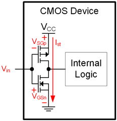
    The reason '0' is read when input is disconnected regardless of pull-up or pull-down is given by the Feed-through issue handling:

    "When a pin is configured as digital input, care has been taken in the nRF52832 design to minimize increased current consumption when the input voltage is between VIL and VIH. However, it is a good practice to ensure that the external circuitry does not drive that pin to levels between VIL and VIH for a long period of time."

    Feed-through is unwanted increase in power by current Ist travelling between Vdd and Gnd not through the input pin but through the input FETs when the input voltage lies within the vanishingly small window where both FETs are slightly turned on:

  • First the latter point of a 200k pull-down resistor not holding the pin low; the internal pull-up NRF_GPIO_PIN_PULLUP is typically 13k so a 200k external resistor to Gnd will not pull down the input pin voltage far enough to fall below the '0' threshold, so reporting '1' is correct.

    I did recognize 13k internal pull resistor so I expected the exactly the same results to be observed both on PCA10040 & my custom board. For discussion on Devzone I guess sticking to official EVBs will do better.

Reply
  • First the latter point of a 200k pull-down resistor not holding the pin low; the internal pull-up NRF_GPIO_PIN_PULLUP is typically 13k so a 200k external resistor to Gnd will not pull down the input pin voltage far enough to fall below the '0' threshold, so reporting '1' is correct.

    I did recognize 13k internal pull resistor so I expected the exactly the same results to be observed both on PCA10040 & my custom board. For discussion on Devzone I guess sticking to official EVBs will do better.

Children
No Data
Related