This post is older than 2 years and might not be relevant anymore
More Info: Consider searching for newer posts

Trying to convert my NRF52840 DK project to run on the NRF52840 Dongle

Win10 + Segger embedded studio

I can get the pca10059 blinky example to work. (C:\nRF5_SDK_15.3.0_59ac345\examples\peripheral\blinky ) 

I use the NRF connect Programmer app to upload the hex file. 

I decided to convert my existing project to run on the dongle by following the instructions on this page https://devzone.nordicsemi.com/nordic/short-range-guides/b/getting-started/posts/nrf52840-dongle-programming-tutorial . I also commenting out my code and pasted the blinky code just to get something recognisable.

I upload hex files for my application and I also needed to upload the hex file for the soft device (C:\nRF5_SDK_15.3.0_59ac345\components\softdevice\s140\hex\s140_nrf52_6.1.1_softdevice.hex)

It doesn't work.

When I add the hex for the soft device I see this
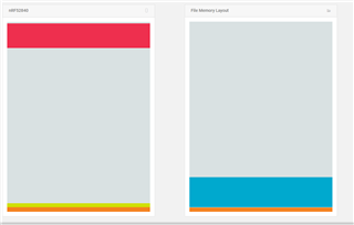
LEFT side

Red is the bootloader, hover text says address range E0000 - FE0000

Lime green is Blinky app and hover text says address range 1000 - 171C

Orange is MBR 0-1000 (4096 size)

RIGHT side

blue is soft device NRF52 s140 6.1.1 0x1000 - 0x25DE8

Orange is "MBR or Application" and shows 0x0-0xB00

When I add the release mode hex file from building the project I see
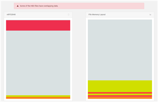
I add the softdevice first and then the application hex.

I started looking for differences between the stuff in C:\nRF5_SDK_15.3.0_59ac345\examples\peripheral\blinky and my project.

I notice that FLASH_SIZE is different in the emProject files.

C:\nRF5_SDK_15.3.0_59ac345\examples\peripheral\blinky\pca10059\mbr\ses\blinky_pca10059_mbr.emProject

linker_section_placement_macros="FLASH_PH_START=0x0;FLASH_PH_SIZE=0x100000;RAM_PH_START=0x20000000;RAM_PH_SIZE=0x40000;FLASH_START=0x1000;FLASH_SIZE=0xff000;RAM_START=0x20000008;RAM_SIZE=0x3fff8"

Values in my project (from dongle programming tutorial.)

linker_section_placement_macros="FLASH_PH_START=0x0;FLASH_PH_SIZE=0x100000;RAM_PH_START=0x20000000;RAM_PH_SIZE=0x40000;FLASH_START=0x1000;FLASH_SIZE=0xDF000;RAM_START=0x20000008;RAM_SIZE=0x3FFF8"

When I change my project to use FLASH_SIZE = FF000

I see this
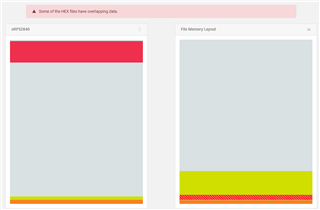
Different, but still not right.

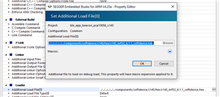
I also see  debug_additional_load_file="../../../../../../components/softdevice/mbr/nrf52840/hex/mbr_nrf52_2.4.1_mbr.hex" in the blinky example but 

debug_additional_load_file="../../../../../../components/softdevice/s140/hex/s140_nrf52_6.1.1_softdevice.hex" in my project. 

I cant see how to add the MBR.hex to my project. It looks like this.
The other file that seems relevant is flash_placement.xml and I see a host of differences but mostly just extra sections in my project for ble things 

I'm a bit stuck. Any help is appreciated. 

-Jason

Parents
  • I tried changing my project to have debug_additional_load_file  mbr_nrf52_2.4.1_mbr.hex instead of s140_nrf52_6.1.1_softdevice.hex but it made no difference. Which I guess is obvious because the the dongle doesn't have debug support.

    I notice that if I try to upload just my application.hex without adding the softdevice.hex then it actually works. My code is running now. I can change the blink speed in my project and it works on the dongle.

    My actual application needs the softdevice though so I still need to figure out how to get the memory laid out correctly.

Reply
  • I tried changing my project to have debug_additional_load_file  mbr_nrf52_2.4.1_mbr.hex instead of s140_nrf52_6.1.1_softdevice.hex but it made no difference. Which I guess is obvious because the the dongle doesn't have debug support.

    I notice that if I try to upload just my application.hex without adding the softdevice.hex then it actually works. My code is running now. I can change the blink speed in my project and it works on the dongle.

    My actual application needs the softdevice though so I still need to figure out how to get the memory laid out correctly.

Children
  • Jason said:
    Which I guess is obvious because the the dongle doesn't have debug support.

    You can debug the dongle by using a DK's OB debugger. Though you need to either populate the debug port connector footprint at the bottom of the dongle, or solder a couple of wires to VDD, GND, SWDIO, and SWDCLK. Then you do not even need a bootloader. 

    See the dongle's Hardware drawings

  • YES, I've been 'debugging' by flashing LED's. oldschool.

    I realised last night that there are 3 debug interfaces but I've not got the 5x2 pin header that I need to solder on, nor do I have the cool needle pin segger cable. (I got the segger edu mini as well as the normal 52840 Dev Kit.) And I'm not sure where I'm supposed to solder the SWDCLK and SWDIO connections to on the NRF52840 Dev Kit. I cant see SWDCLK and SWDIO except on the tiny debug headers. 

    Anyway, by flashing LEDs I found that my app crashes when I call nrf_sdh_enable_request() and that this means it's something to do with the RAM layout, as you say in your answer below. (I cannot see how I can reply to that comment, only this one.) I found other forum users talking about similar problems related to their calls to nrf_sdh_enable_request() crashing.

    I've used a diff program to compare my project file with the ble_beacon project file. and taken all of the settings that looked relevant. I was able run the ble_blinky 10059 example and it runs fine. I can see it in nrf connect on my android phone

    I made project -> options -> Build->"Memory segments" match the settings in ble_app_blinky_pca10059

    • FLASH RX 0x0 0x100000;RAM RWX 0x20000000 0x40000

    Also the project -> options -> Linker -> Section Placement Macros 

    • FLASH_PH_START=0x0
    • FLASH_PH_SIZE=0x100000
    • RAM_PH_START=0x20000000
    • RAM_PH_SIZE=0x40000
    • FLASH_START=0x26000
    • FLASH_SIZE=0xda000
    • RAM_START=0x200022e0
    • RAM_SIZE=0x3dd20

    I also checked that the flash_placement.xml files are identical

    It still fails in the call to nrf_sdh_enable_request()

    Of course my app is different from the ble_blinky_10059 example so maybe I need to do more than just copy the settings from that example. 

    I see in this comment that maybe I should look at the softdevice specification

    https://devzone.nordicsemi.com/f/nordic-q-a/27219/unable-to-enable-the-softdevice-on-custom-board/107375#107375

    So I looked at the spec but I couldnt see what they were referring to.

    https://infocenter.nordicsemi.com/topic/struct_nrf52/struct/s140.html

  • Jason said:
    I cant see SWDCLK and SWDIO except on the tiny debug headers. 

     They are the two weird plated indentations on the neck of the USB plug. See the hardware drawings I posted previously.

    Jason said:
    It still fails in the call to nrf_sdh_enable_request()

     If you enable the log module it will spit out the proper RAM settings when you call nrf_sdh_enable_request. 

    Jason said:
    Of course my app is different from the ble_blinky_10059 example so maybe I need to do more than just copy the settings from that example. 

     I strongly urge you to use an existing BLE example project as the basis for any project that uses BLE.

  •  I strongly urge you to use an existing BLE example project as the basis for any project that uses BLE

    Absolutely!!

  • Thanks, yes I did this, sort-of.

    I edited ble_app_beacon_pca10056 to make my current project in. Now I need to either bring in the differences from pca10059 blinky or move my changes into the pca10059 blinky. I just thought it was probably similar work either way.

Related