This post is older than 2 years and might not be relevant anymore
More Info: Consider searching for newer posts

Reading High impedance via GPIO pin

Dear sir,

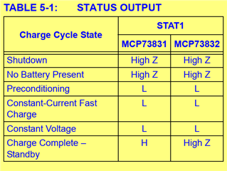
We have interfaced a charger ic with NRF52832. It is having a charging status pin to show completion of charge. It is having 3 states 

1. High impedance (Battery not present or module shut down)

2. Low (Charging)

3. High (Charge complete).

I am configuring the corresponding GPIO (GPIO 29) using the function " nrf_gpio_cfg_input" and trying to read using the function "nrf_gpio_pin_read". 

But my question is whether it is possible to read High impedance state.
thanks & regards,

Kotteeswaran.E

  • No: In input mode, GPIO is a digital input,  so it can only read 'high' or 'low' = '1' or '0'.

    To read a 3rd state, you'd need to do something analogue.

    The same would apply to any microcontroller - it's not specific to Nordic or nRF52.

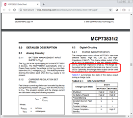
    Presumably, this pin is intended to drive the midpoint of a pair of series-connected LEDs  so that either one or the other will be on - or neither in the Hi-Z state?

    You should contact the chip manufacturer to see if they have any recommendations for connecting this to a microcontroller ...

  • Presumably, this pin is intended to drive the midpoint of a pair of series-connected LEDs

    Indeed that's what the datasheet says:

  • Hi,

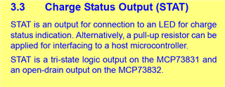
    MCP73831 has high output level of STAT signal close to its supply voltage (charging voltage). GPIO pins of nrf52832 are limited by VDD+0.3V. Don't connect STAT pin of 73831 to GPIO directly - either use 73832 with pull-up, or add a voltage divider.

  • Yes it is possible to infer high-impedance state. With MCP73831 a high-resistance voltage divider is required to keep the input voltage within acceptable range (as mentioned by Dmitry). With the input pin connected to the divider mid-point read the port pin twice, once with PULLDOWN enabled and once with PULLUP enabled on the port pin. If the MCP73831 is driving low, both reads will return '0'. If the MCP73831 is driving high both reads will return '1'. If the MCP73831 is High Z the first read will be '0' and the second '1'. Allow time for any distributed capacitance to charge/discharge, perhaps a few uSecs after changing the pull-down/pull-up before reading the pin..

    Edit: note the resistance divider has to be low enough to prevent the 13k internal pull-up or pull-down from holding above or below the 0/1 input thresholds when the charger drives L or H; 2 x about 2k would work but that sacrifices over 1 mA through the divider.

Related