This post is older than 2 years and might not be relevant anymore
More Info: Consider searching for newer posts

How can we flash the original factory (out-of-the-box) FW for the nRF9160?

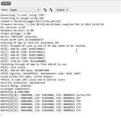
Somehow my nRF9160 DK board has become essentially unresponsive. Flashing new modem using nRF Connect Programmer, and downloaded nRF FW,  "seem" to work. But nothing else. No signal can be seen, no AT command response, no LED 3/4 are ever on. So it's impossible to know what happened. So this possibly due to lacking instructions in how to setup the device?

How can we flash the original factory (out-of-the-box) FW for the nRF9160 DK board?

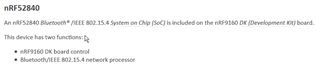
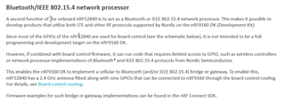
(a) Do we need to flash also the on-board nRF82840? (How to tell the difference what is getting flashed?)

(b) Where is the correct FW to flash for my board? 

Parents
  • Hi E3V3A,

    Please try to do the following:

    1. Make sure you use the latest west tool:

    pip3 install west --upgrade

    2. Then let's make sure that the NCS is set up correctly:

    cd ncs/nrf
    git checkout master
    git pull
    git checkout v1.0.0
    west update

    3. Then delete the build folder in the asset tracker folder.

    4. Open Segger Embedded studio and click File --> Open nRF Connect SDK project

    If you get an error please share the Output from the terminal:


    You should not need to mess with any other settings that you described in your last post.


    The board controller FW on the nRF52 is just routing the different signals from the nRF91 either out to the external pins or VCOM ports. (That would be flashed in the nrf52 Flash.)
    see more info in the documentation.

    The modem firmware is saved in the modem flash, and the applications that you flash to nrf91 is flashed to the applications' own flash.

    best regards,

    Martin L.

Reply
  • Hi E3V3A,

    Please try to do the following:

    1. Make sure you use the latest west tool:

    pip3 install west --upgrade

    2. Then let's make sure that the NCS is set up correctly:

    cd ncs/nrf
    git checkout master
    git pull
    git checkout v1.0.0
    west update

    3. Then delete the build folder in the asset tracker folder.

    4. Open Segger Embedded studio and click File --> Open nRF Connect SDK project

    If you get an error please share the Output from the terminal:


    You should not need to mess with any other settings that you described in your last post.


    The board controller FW on the nRF52 is just routing the different signals from the nRF91 either out to the external pins or VCOM ports. (That would be flashed in the nrf52 Flash.)
    see more info in the documentation.

    The modem firmware is saved in the modem flash, and the applications that you flash to nrf91 is flashed to the applications' own flash.

    best regards,

    Martin L.

Children
  • Thank you Martin!

    Following your detailed instructions made it quite easy!
    The only issue was that you need to force the git checkout to discard old cruft.

    git checkout -f master
    

    As for the rest, I'll fill in the blanks:

    - Follow the steps (by Martin) above. I'll try to clarify some of that. If you have cleaned out the build directories and have a semi-pristine EmStudio, then when you start it, it should look like this:


    Enter the info as suggested:

    This will load the project and add all the relevant files.
    If successful it should look like this:

    Now the project is ready to be built. Select:
    Build > Build Solution  (or simply press Shift+F7)

    This will compile the project and create the HEX files:

    $ cd "C:\NordicS\ncs\nrf\applications\asset_tracker"
    $ find ./ -iname "*.hex"
    ./build_nrf9160_pca10090ns/spm/zephyr/zephyr.hex
    ./build_nrf9160_pca10090ns/zephyr/merged.hex
    ./build_nrf9160_pca10090ns/zephyr/zephyr.hex
    
    # Welcome to Cygwin! :)
    

    Opening the project folder, you should see the merged.hex file, that you can use to flash the asset_tracker.
    You can use the nRF Connect - Programmer to do this, but you can also do it within the EmStudio by connecting the J-Link and "download" the HEX file. (Here "download" means, download from your PC to the nRF9160 DK).

    Do this:

    (a) connect the J-Link programmer:

    (b) "Download" the HEX file to your "target":

    The output should be:

    You can now fire up your nRF Connector - LTE Link Monitor and everything should work.

    The hardest part is to get the LTE connection with the provided iBasis SIM card...


  • (a) So the nRF52? controller knows where to put the HEX files when flashed, without having to use SW5 to flip to nRF52?

    It seem like a pretty cool device.


    (b) Can you please explain the function of the "Section Placement" in the project setting picture above?

  • Hi E3V3A,

    a) The nRF52840 on the nRF91DK works as a board controller and has its own firmware. (code)

    If you are going to flash something to the nRF52 device you need to switch SW5 to nrf52 so the Debug/programmer is routed correctly.

    b) Section Placement documentation

    you should not need to change it

Related