This post is older than 2 years and might not be relevant anymore
More Info: Consider searching for newer posts

nRF9160 DK Current Measurement

I would like to confirm what I'm seeing on my setup trying to measure current with the nRF9160 DK.

I'm using an oscilloscope and am following the instructions in the latest user guide for such measurements.  I have a DK that is version 0.8.5.  I'm just running the asset_tracker application and am not trying to force the 9160 into any particular mode at this point.  Just need to confirm what I'm seeing.

Here is an example of what I believe is happening on transmit
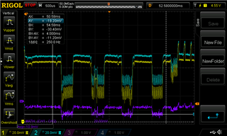
Example

So, the yellow trace, channel 1, is connected to P24 on the uppermost pin (vdd nrf?) and the white trace, channel 2, is on the middle pin of P24.  The bottom trace is a math function, ch1 - ch2.

Another example:

Another example

One thing I'd like to confirm is that I should be seeing that topmost pin drop below the middle pin voltage when current is being drawn.  I was expecting that pin to stay more steady in voltage and the second pin to drop in voltage.  Does this seem correct to you?

Thank you,

Erik

  • This looks similar to what I get here. Since the measurement resistor is only 0.5 Ohm, the voltage drop over the resistor is very small, smaller than the voltage drop in the path from the source to the measurement resistor (channel 1). Be aware that it's very hard to get accurate measurements on low currents (idle currents in the uA range) using this technique. You would have to increase the resistor to about 10-20 Ohm, but then you would get too high voltage drop during the radio current spikes. So I think it's better to use an amperemeter for lower currents. Or a power analyzer.

  • Thanks Stian, for explaining why both voltages drop when transmitting.  But to confirm things, Channel 1 is dropping below Channel 2 when transmitting.  Is that right?

    Thanks,

    Erik

  • Also, Stian, you mention the voltage drop over the resistor being small compared to the voltage drop from the source to the measurement resistor.  Channel 1 is read at that topmost pin of P24, which is labeled VDD_nRF.  Even if there is a voltage drop from the external power supply applied to P28, it still seems like that topmost pin of P24 would remain pretty steady.  Before putting more effort into measuring currents, I want to be sure I'm doing so correctly.

  • I'm currently out of office, but will be back on Wednesday this week. Then I can do some measurements on the scope and compare them with the power analyzer so we can see how reliable this scope setup is.

    I mixed up channel 1 and 2 in my previous answer. So ch2 is on the power supply side of the measurement resistor, and ch1 is on the nRF side (VDD_nRF). Ch1 voltage is expected to drop even further than ch2 when current flows through the resistor. And the resulting current going through the resistor is (V_ch2 - V_ch1) / R. (So you need to invert the math function)

  • Thanks for the response.

    Interesting because I have Ch1 connected to the uppermost pin on P24, which I thought was the power supply side.  But I see it dropping below the middle pin of P24.  That is one of the observations I was questioning.

Related