
Hi,
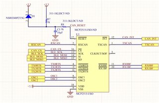
I'm trying to use the nrf_drv_spi.c to communicate with a BL652 + MCP2515 CAN SPI custom device. I've connected the MCP2515 to the nRF52832 (BL652 module) in the following way with SCLK = P0.25, SPI_MISO_PIN = P0.24, SPI_MOSI_PIN = P0.23 and SPI_SS_PIN = P0.05 and a 16MHz resonator. I've tested the power and the osc clock signal. Both of these test out fine with my oscilloscope.
I've taken the following arduino .cpp code and started modifying to work with the nRF52832 and the nrf_drv_spi driver. https://github.com/Seeed-Studio/CAN_BUS_Shield/blob/master/mcp_can.cpp. Most functions are commented out presently as I'm trying to get the basics to work.
The attached is my main.c, mcp_can.c, mcp_can.h and mcp_can_dfs.h.
/* mcp2515_can.c mcp_can.h 2012 Copyright (c) Seeed Technology Inc. All right reserved. Author:Loovee ([email protected]) 2014-1-16 Contributor: Cory J. Fowler Latonita Woodward1 Mehtajaghvi BykeBlast TheRo0T Tsipizic ralfEdmund Nathancheek BlueAndi Adlerweb Btetz Hurvajs ttlappalainen The MIT License (MIT) Copyright (c) 2013 Seeed Technology Inc. Permission is hereby granted, free of charge, to any person obtaining a copy of this software and associated documentation files (the "Software"), to deal in the Software without restriction, including without limitation the rights to use, copy, modify, merge, publish, distribute, sublicense, and/or sell copies of the Software, and to permit persons to whom the Software is furnished to do so, subject to the following conditions: The above copyright notice and this permission notice shall be included in all copies or substantial portions of the Software. THE SOFTWARE IS PROVIDED "AS IS", WITHOUT WARRANTY OF ANY KIND, EXPRESS OR IMPLIED, INCLUDING BUT NOT LIMITED TO THE WARRANTIES OF MERCHANTABILITY, FITNESS FOR A PARTICULAR PURPOSE AND NONINFRINGEMENT. IN NO EVENT SHALL THE AUTHORS OR COPYRIGHT HOLDERS BE LIABLE FOR ANY CLAIM, DAMAGES OR OTHER LIABILITY, WHETHER IN AN ACTION OF CONTRACT, TORT OR OTHERWISE, ARISING FROM, OUT OF OR IN CONNECTION WITH THE SOFTWARE OR THE USE OR OTHER DEALINGS IN THE SOFTWARE. */ #include "mcp_can.h" #include "nrf_delay.h" #include "nrf_drv_spi.h" #include "app_timer.h" #include "nrf_gpio.h" #include "nrf_log.h" #include "nrf_log_ctrl.h" #include "nrf_log_default_backends.h" #define TICKS_PER_MS APP_TIMER_TICKS(1) //#define spi_readwrite pSPI->transfer //#define spi_read() spi_readwrite(0x00) //#define spi_write(spi_val) spi_readwrite(spi_val) //#define SPI_BEGIN() pSPI->beginTransaction(SPISettings(10000000, MSBFIRST, SPI_MODE0)) //#define SPI_END() pSPI->endTransaction() mcp2515_can_t m_mcp_can; uint8_t dummy_receive; #define SPI_CAN_INSTANCE 0 /**< SPI instance index. */ static const nrf_drv_spi_t can_spi = NRF_DRV_SPI_INSTANCE(SPI_CAN_INSTANCE); /**< SPI instance. */ static volatile bool spi_xfer_done; /**< Flag used to indicate that SPI instance completed the transfer. */ uint32_t millis() { return (app_timer_cnt_get() / TICKS_PER_MS); } /********************************************************************************************************* ** Function name: mcp2515_spi_handler ** Descriptions: select the device through cs -> LOW *********************************************************************************************************/ void spi_can_event_handler(nrf_drv_spi_evt_t const * p_event, void * p_context) { switch(p_event->type) { case NRF_DRV_SPI_EVENT_DONE: spi_xfer_done = true; NRF_LOG_INFO("Transfer completed."); /* if (m_rx_buf[0] != 0) { NRF_LOG_INFO(" Received:"); NRF_LOG_HEXDUMP_INFO(m_rx_buf, strlen((const char *)m_rx_buf)); } */ break; default: break; } } /********************************************************************************************************* ** Function name: mcp2515_spi_initialization ** Descriptions: initialize the spi bus through nrf_drv_spi.h *********************************************************************************************************/ void mcp2515_can_initialize() { uint32_t err_code; nrf_drv_spi_config_t spi_config = NRF_DRV_SPI_DEFAULT_CONFIG; spi_config.frequency = NRF_DRV_SPI_FREQ_4M; spi_config.mode = NRF_DRV_SPI_MODE_2; spi_config.ss_pin = SPI_SS_PIN; spi_config.miso_pin = SPI_MISO_PIN; spi_config.mosi_pin = SPI_MOSI_PIN; spi_config.sck_pin = SPI_SCK_PIN; spi_config.bit_order = NRF_DRV_SPI_BIT_ORDER_MSB_FIRST; //spi_config.bit_order = (lsb ? NRF_DRV_SPI_BIT_ORDER_LSB_FIRST : NRF_DRV_SPI_BIT_ORDER_MSB_FIRST); //if(!nrf_drv_spi_init(&can_spi, &spi_config, spi_can_event_handler, NULL)) //{ //err_code = nrf_drv_spi_init(&spi_master_instance, &spi_config, spi_master_event_handler, NULL); //APP_ERROR_CHECK(err_code); //} err_code = nrf_drv_spi_init(&can_spi, &spi_config, spi_can_event_handler, NULL); APP_ERROR_CHECK(err_code); NRF_LOG_INFO("CAN SPI example started."); } /********************************************************************************************************* ** Function name: mcp2515_spi_transfer ** Descriptions: nRF52832 spi transer (send and receive) *********************************************************************************************************/ void mcp2515_spi_transfer(uint8_t p_tx_data, uint8_t p_rx_data, const uint16_t len) { // Initalize buffers. // Start transfer. //uint32_t err_code = NRF_SUCCESS; // Reset rx buffer and transfer done flag memset(&p_rx_data, 0, len); NRF_LOG_INFO("tx data %x\n", p_tx_data); APP_ERROR_CHECK(nrf_drv_spi_transfer(&can_spi, &p_tx_data, len, &p_rx_data, len)); while (!spi_xfer_done) { __WFE(); } spi_xfer_done = false; //spi_master_send_recv(spi_master_hw_instance, &tx_data, len, &p_rx_data, len); NRF_LOG_INFO("rx data %x\n", p_rx_data); //APP_ERROR_CHECK(err_code); } /********************************************************************************************************* ** Function name: mcp2515_select ** Descriptions: select the device through cs -> LOW *********************************************************************************************************/ void MCP2515_SELECT() { nrf_gpio_pin_clear(m_mcp_can.can_spi_cs); } /********************************************************************************************************* ** Function name: mcp2515_unselect ** Descriptions: unselect the device through cs -> HIGH *********************************************************************************************************/ void MCP2515_UNSELECT() { nrf_gpio_pin_set(m_mcp_can.can_spi_cs); } /********************************************************************************************************* ** Function name: txCtrlReg ** Descriptions: return tx ctrl reg according to tx buffer index. ** According to my tests this is faster and saves memory compared using vector *********************************************************************************************************/ /* byte txCtrlReg(byte i) { switch (i) { case 0: return MCP_TXB0CTRL; case 1: return MCP_TXB1CTRL; case 2: return MCP_TXB2CTRL; } return MCP_TXB2CTRL; } */ /********************************************************************************************************* ** Function name: statusToBuffer ** Descriptions: converts CANINTF status to tx buffer index *********************************************************************************************************/ /* byte statusToTxBuffer(byte status) { switch ( status ) { case MCP_TX0IF : return 0; case MCP_TX1IF : return 1; case MCP_TX2IF : return 2; } return 0xff; } */ /********************************************************************************************************* ** Function name: statusToBuffer ** Descriptions: converts CANINTF status to tx buffer sidh *********************************************************************************************************/ /* byte statusToTxSidh(byte status) { switch ( status ) { case MCP_TX0IF : return MCP_TXB0SIDH; case MCP_TX1IF : return MCP_TXB1SIDH; case MCP_TX2IF : return MCP_TXB2SIDH; } return 0; } */ /********************************************************************************************************* ** Function name: txSidhToTxLoad ** Descriptions: return tx load command according to tx buffer sidh register *********************************************************************************************************/ /* byte txSidhToRTS(byte sidh) { switch (sidh) { case MCP_TXB0SIDH: return MCP_RTS_TX0; case MCP_TXB1SIDH: return MCP_RTS_TX1; case MCP_TXB2SIDH: return MCP_RTS_TX2; } return 0; } */ /********************************************************************************************************* ** Function name: txSidhToTxLoad ** Descriptions: return tx load command according to tx buffer sidh register *********************************************************************************************************/ /* byte txSidhToTxLoad(byte sidh) { switch (sidh) { case MCP_TXB0SIDH: return MCP_LOAD_TX0; case MCP_TXB1SIDH: return MCP_LOAD_TX1; case MCP_TXB2SIDH: return MCP_LOAD_TX2; } return 0; } */ /********************************************************************************************************* ** Function name: txIfFlag ** Descriptions: return tx interrupt flag *********************************************************************************************************/ /* byte txIfFlag(byte i) { switch (i) { case 0: return MCP_TX0IF; case 1: return MCP_TX1IF; case 2: return MCP_TX2IF; } return 0; } */ /********************************************************************************************************* ** Function name: txStatusPendingFlag ** Descriptions: return buffer tx pending flag on status *********************************************************************************************************/ /* byte txStatusPendingFlag(byte i) { switch (i) { case 0: return MCP_STAT_TX0_PENDING; case 1: return MCP_STAT_TX1_PENDING; case 2: return MCP_STAT_TX2_PENDING; } return 0xff; } */ /********************************************************************************************************* ** Function name: mcp2515_reset ** Descriptions: reset the device *********************************************************************************************************/ void mcp2515_reset() { #ifdef SPI_HAS_TRANSACTION SPI_BEGIN(); #endif //MCP2515_SELECT(); //mcp2515_spi_transfer(MCP_RESET, dummy_receive, 1); uint8_t m_tx_buf[1] = {MCP_RESET}; uint8_t m_rx_buf[2]; uint8_t m_length = sizeof(m_tx_buf); memset(m_rx_buf, 0, m_length); spi_xfer_done = false; APP_ERROR_CHECK(nrf_drv_spi_transfer(&can_spi, m_tx_buf, m_length, m_rx_buf, m_length)); while (!spi_xfer_done) { __WFE(); } //return m_rx_buf[1]; //spi_readwrite(MCP_RESET); //MCP2515_UNSELECT(); #ifdef SPI_HAS_TRANSACTION SPI_END(); #endif nrf_delay_ms(10); } /********************************************************************************************************* ** Function name: mcp2515_readRegister ** Descriptions: read register *********************************************************************************************************/ uint8_t mcp2515_readRegister(const uint8_t address) { //uint8_t ret; #ifdef SPI_HAS_TRANSACTION SPI_BEGIN(); #endif //MCP2515_SELECT(); uint8_t m_tx_buf[] = {MCP_READ, address}; uint8_t m_rx_buf[sizeof(MCP_READ_STATUS) + 1]; uint8_t m_length = sizeof(m_tx_buf); memset(m_rx_buf, 0, m_length); spi_xfer_done = false; APP_ERROR_CHECK(nrf_drv_spi_transfer(&can_spi, m_tx_buf, m_length, m_rx_buf, m_length)); while (!spi_xfer_done) { __WFE(); } return m_rx_buf[1]; //mcp2515_spi_transfer(MCP_READ, dummy_receive, 1); //mcp2515_spi_transfer(address, dummy_receive, 1); //mcp2515_spi_transfer(0x00, ret, 1); //spi_readwrite(MCP_READ); //spi_readwrite(address); //ret = spi_read(); //MCP2515_UNSELECT(); #ifdef SPI_HAS_TRANSACTION SPI_END(); #endif //return ret; } /********************************************************************************************************* ** Function name: mcp2515_readRegisterS ** Descriptions: read registerS *********************************************************************************************************/ /* void MCP_CAN::mcp2515_readRegisterS(const byte address, byte values[], const byte n) { byte i; #ifdef SPI_HAS_TRANSACTION SPI_BEGIN(); #endif MCP2515_SELECT(); spi_readwrite(MCP_READ); spi_readwrite(address); // mcp2515 has auto-increment of address-pointer for (i=0; i<n && i<CAN_MAX_CHAR_IN_MESSAGE; i++) { values[i] = spi_read(); } MCP2515_UNSELECT(); #ifdef SPI_HAS_TRANSACTION SPI_END(); #endif } */ /********************************************************************************************************* ** Function name: mcp2515_setRegister ** Descriptions: set register *********************************************************************************************************/ void mcp2515_setRegister(const uint8_t address, const uint8_t value) { #ifdef SPI_HAS_TRANSACTION SPI_BEGIN(); #endif //MCP2515_SELECT(); //mcp2515_spi_transfer(MCP_WRITE, dummy_receive, 1); //mcp2515_spi_transfer(address, dummy_receive, 1); //mcp2515_spi_transfer(value, dummy_receive, 1); uint8_t m_tx_buf[3] = {MCP_WRITE, address, value}; uint8_t m_rx_buf[4]; uint8_t m_length = sizeof(m_tx_buf); memset(m_rx_buf, 0, m_length); spi_xfer_done = false; APP_ERROR_CHECK(nrf_drv_spi_transfer(&can_spi, m_tx_buf, m_length, m_rx_buf, m_length)); while (!spi_xfer_done) { __WFE(); } //return m_rx_buf[1]; //spi_readwrite(MCP_WRITE); //spi_readwrite(address); //spi_readwrite(value); //MCP2515_UNSELECT(); #ifdef SPI_HAS_TRANSACTION SPI_END(); #endif } /********************************************************************************************************* ** Function name: mcp2515_setRegisterS ** Descriptions: set registerS *********************************************************************************************************/ /* void MCP_CAN::mcp2515_setRegisterS(const byte address, const byte values[], const byte n) { byte i; #ifdef SPI_HAS_TRANSACTION SPI_BEGIN(); #endif MCP2515_SELECT(); spi_readwrite(MCP_WRITE); spi_readwrite(address); for (i=0; i<n; i++) { spi_readwrite(values[i]); } MCP2515_UNSELECT(); #ifdef SPI_HAS_TRANSACTION SPI_END(); #endif } */ /********************************************************************************************************* ** Function name: mcp2515_modifyRegister ** Descriptions: set bit of one register *********************************************************************************************************/ void mcp2515_modifyRegister(const uint8_t address, const uint8_t mask, const uint8_t data) { #ifdef SPI_HAS_TRANSACTION SPI_BEGIN(); #endif //MCP2515_SELECT(); //mcp2515_spi_transfer(MCP_BITMOD, dummy_receive, 1); //mcp2515_spi_transfer(address, dummy_receive, 1); //mcp2515_spi_transfer(mask, dummy_receive, 1); //mcp2515_spi_transfer(data, dummy_receive, 1); uint8_t m_tx_buf[4] = {MCP_BITMOD, address, mask, data}; uint8_t m_rx_buf[5]; uint8_t m_length = sizeof(m_tx_buf); memset(m_rx_buf, 0, m_length); spi_xfer_done = false; APP_ERROR_CHECK(nrf_drv_spi_transfer(&can_spi, m_tx_buf, m_length, m_rx_buf, m_length)); while (!spi_xfer_done) { __WFE(); } //return m_rx_buf[1]; //spi_readwrite(MCP_BITMOD); //spi_readwrite(address); //spi_readwrite(mask); //spi_readwrite(data); //MCP2515_UNSELECT(); #ifdef SPI_HAS_TRANSACTION SPI_END(); #endif } /********************************************************************************************************* ** Function name: mcp2515_readStatus ** Descriptions: read mcp2515's Status *********************************************************************************************************/ uint8_t mcp2515_readStatus(void) { //uint8_t i; #ifdef SPI_HAS_TRANSACTION SPI_BEGIN(); #endif //MCP2515_SELECT(); uint8_t m_tx_buf[] = {MCP_READ_STATUS}; uint8_t m_rx_buf[sizeof(MCP_READ_STATUS) + 1]; uint8_t m_length = sizeof(m_tx_buf); memset(m_rx_buf, 0, m_length); spi_xfer_done = false; APP_ERROR_CHECK(nrf_drv_spi_transfer(&can_spi, m_tx_buf, m_length, m_rx_buf, m_length)); while (!spi_xfer_done) { __WFE(); } return m_rx_buf[1]; //mcp2515_spi_transfer(MCP_READ_STATUS, dummy_receive, 1); //mcp2515_spi_transfer(0x00, i, 1); /* spi_readwrite(MCP_READ_STATUS); i = spi_read(); */ //MCP2515_UNSELECT(); #ifdef SPI_HAS_TRANSACTION SPI_END(); #endif //return i; } /********************************************************************************************************* ** Function name: setSleepWakeup ** Descriptions: Enable or disable the wake up interrupt (If disabled the MCP2515 will not be woken up by CAN bus activity) *********************************************************************************************************/ /* void MCP_CAN::setSleepWakeup(const byte enable) { mcp2515_modifyRegister(MCP_CANINTE, MCP_WAKIF, enable ? MCP_WAKIF : 0); } */ /********************************************************************************************************* ** Function name: sleep ** Descriptions: Put mcp2515 in sleep mode to save power *********************************************************************************************************/ /* byte MCP_CAN::sleep() { if(getMode() != MODE_SLEEP) return mcp2515_setCANCTRL_Mode(MODE_SLEEP); else return CAN_OK; } */ /********************************************************************************************************* ** Function name: wake ** Descriptions: wake MCP2515 manually from sleep. It will come back in the mode it was before sleeping. *********************************************************************************************************/ /* byte MCP_CAN::wake() { byte currMode = getMode(); if(currMode != mcpMode) return mcp2515_setCANCTRL_Mode(mcpMode); else return CAN_OK; } */ /********************************************************************************************************* ** Function name: mcp2515_requestNewMode ** Descriptions: Set control mode *********************************************************************************************************/ uint8_t mcp2515_requestNewMode(const uint8_t newmode) { unsigned long startTime = millis(); // Spam new mode request and wait for the operation to complete while(1) { // Request new mode // This is inside the loop as sometimes requesting the new mode once doesn't work (usually when attempting to sleep) mcp2515_modifyRegister(MCP_CANCTRL, MODE_MASK, newmode); uint8_t statReg = mcp2515_readRegister(MCP_CANSTAT); if((statReg & MODE_MASK) == newmode){ // We're now in the new mode return MCP2515_OK; } else if((millis() - startTime) > 200){ // Wait no more than 200ms for the operation to complete return MCP2515_FAIL; } } } /********************************************************************************************************* ** Function name: getMode ** Descriptions: Returns current control mode *********************************************************************************************************/ uint8_t getMode() { return mcp2515_readRegister(MCP_CANSTAT) & MODE_MASK; } /********************************************************************************************************* ** Function name: mcp2515_setCANCTRL_Mode ** Descriptions: set control mode *********************************************************************************************************/ uint8_t mcp2515_setCANCTRL_Mode(const uint8_t newmode) { // If the chip is asleep and we want to change mode then a manual wake needs to be done // This is done by setting the wake up interrupt flag // This undocumented trick was found at https://github.com/mkleemann/can/blob/master/can_sleep_mcp2515.c if((getMode()) == MODE_SLEEP && newmode != MODE_SLEEP) { // Make sure wake interrupt is enabled uint8_t wakeIntEnabled = (mcp2515_readRegister(MCP_CANINTE) & MCP_WAKIF); if(!wakeIntEnabled){ mcp2515_modifyRegister(MCP_CANINTE, MCP_WAKIF, MCP_WAKIF); } // Set wake flag (this does the actual waking up) mcp2515_modifyRegister(MCP_CANINTF, MCP_WAKIF, MCP_WAKIF); // Wait for the chip to exit SLEEP and enter LISTENONLY mode. // If the chip is not connected to a CAN bus (or the bus has no other powered nodes) it will sometimes trigger the wake interrupt as soon // as it's put to sleep, but it will stay in SLEEP mode instead of automatically switching to LISTENONLY mode. // In this situation the mode needs to be manually set to LISTENONLY. if(mcp2515_requestNewMode(MODE_LISTENONLY) != MCP2515_OK){ return MCP2515_FAIL; } // Turn wake interrupt back off if it was originally off if(!wakeIntEnabled){ mcp2515_modifyRegister(MCP_CANINTE, MCP_WAKIF, 0); } } // Clear wake flag mcp2515_modifyRegister(MCP_CANINTF, MCP_WAKIF, 0); return mcp2515_requestNewMode(newmode); } /********************************************************************************************************* ** Function name: setMode ** Descriptions: Sets control mode *********************************************************************************************************/ uint8_t setMode(const uint8_t opMode) { //if(opMode != MODE_SLEEP) // if going to sleep, the value stored in opMode is not changed so that we can return to it later //mcpMode = opMode; if(opMode != MODE_SLEEP) { m_mcp_can.can_mcpMode = opMode; } return mcp2515_setCANCTRL_Mode(opMode); } /********************************************************************************************************* ** Function name: mcp2515_configRate ** Descriptions: set baudrate *********************************************************************************************************/ uint8_t mcp2515_configRate(const uint8_t canSpeed, const uint8_t clock) { uint8_t set, cfg1, cfg2, cfg3; set = 1; switch (clock) { case (MCP_16MHz) : switch (canSpeed) { case (CAN_5KBPS): cfg1 = MCP_16MHz_5kBPS_CFG1; cfg2 = MCP_16MHz_5kBPS_CFG2; cfg3 = MCP_16MHz_5kBPS_CFG3; break; case (CAN_10KBPS): cfg1 = MCP_16MHz_10kBPS_CFG1; cfg2 = MCP_16MHz_10kBPS_CFG2; cfg3 = MCP_16MHz_10kBPS_CFG3; break; case (CAN_20KBPS): cfg1 = MCP_16MHz_20kBPS_CFG1; cfg2 = MCP_16MHz_20kBPS_CFG2; cfg3 = MCP_16MHz_20kBPS_CFG3; break; case (CAN_25KBPS): cfg1 = MCP_16MHz_25kBPS_CFG1; cfg2 = MCP_16MHz_25kBPS_CFG2; cfg3 = MCP_16MHz_25kBPS_CFG3; break; case (CAN_31K25BPS): cfg1 = MCP_16MHz_31k25BPS_CFG1; cfg2 = MCP_16MHz_31k25BPS_CFG2; cfg3 = MCP_16MHz_31k25BPS_CFG3; break; case (CAN_33KBPS): cfg1 = MCP_16MHz_33kBPS_CFG1; cfg2 = MCP_16MHz_33kBPS_CFG2; cfg3 = MCP_16MHz_33kBPS_CFG3; break; case (CAN_40KBPS): cfg1 = MCP_16MHz_40kBPS_CFG1; cfg2 = MCP_16MHz_40kBPS_CFG2; cfg3 = MCP_16MHz_40kBPS_CFG3; break; case (CAN_50KBPS): cfg1 = MCP_16MHz_50kBPS_CFG1; cfg2 = MCP_16MHz_50kBPS_CFG2; cfg3 = MCP_16MHz_50kBPS_CFG3; break; case (CAN_80KBPS): cfg1 = MCP_16MHz_80kBPS_CFG1; cfg2 = MCP_16MHz_80kBPS_CFG2; cfg3 = MCP_16MHz_80kBPS_CFG3; break; case (CAN_83K3BPS): cfg1 = MCP_16MHz_83k3BPS_CFG1; cfg2 = MCP_16MHz_83k3BPS_CFG2; cfg3 = MCP_16MHz_83k3BPS_CFG3; break; case (CAN_95KBPS): cfg1 = MCP_16MHz_95kBPS_CFG1; cfg2 = MCP_16MHz_95kBPS_CFG2; cfg3 = MCP_16MHz_95kBPS_CFG3; break; case (CAN_100KBPS): cfg1 = MCP_16MHz_100kBPS_CFG1; cfg2 = MCP_16MHz_100kBPS_CFG2; cfg3 = MCP_16MHz_100kBPS_CFG3; break; case (CAN_125KBPS): cfg1 = MCP_16MHz_125kBPS_CFG1; cfg2 = MCP_16MHz_125kBPS_CFG2; cfg3 = MCP_16MHz_125kBPS_CFG3; break; case (CAN_200KBPS): cfg1 = MCP_16MHz_200kBPS_CFG1; cfg2 = MCP_16MHz_200kBPS_CFG2; cfg3 = MCP_16MHz_200kBPS_CFG3; break; case (CAN_250KBPS): cfg1 = MCP_16MHz_250kBPS_CFG1; cfg2 = MCP_16MHz_250kBPS_CFG2; cfg3 = MCP_16MHz_250kBPS_CFG3; break; case (CAN_500KBPS): cfg1 = MCP_16MHz_500kBPS_CFG1; cfg2 = MCP_16MHz_500kBPS_CFG2; cfg3 = MCP_16MHz_500kBPS_CFG3; break; case (CAN_666KBPS): cfg1 = MCP_16MHz_666kBPS_CFG1; cfg2 = MCP_16MHz_666kBPS_CFG2; cfg3 = MCP_16MHz_666kBPS_CFG3; break; case (CAN_1000KBPS): cfg1 = MCP_16MHz_1000kBPS_CFG1; cfg2 = MCP_16MHz_1000kBPS_CFG2; cfg3 = MCP_16MHz_1000kBPS_CFG3; break; default: set = 0; break; } break; case (MCP_8MHz) : switch (canSpeed) { case (CAN_5KBPS) : cfg1 = MCP_8MHz_5kBPS_CFG1; cfg2 = MCP_8MHz_5kBPS_CFG2; cfg3 = MCP_8MHz_5kBPS_CFG3; break; case (CAN_10KBPS) : cfg1 = MCP_8MHz_10kBPS_CFG1; cfg2 = MCP_8MHz_10kBPS_CFG2; cfg3 = MCP_8MHz_10kBPS_CFG3; break; case (CAN_20KBPS) : cfg1 = MCP_8MHz_20kBPS_CFG1; cfg2 = MCP_8MHz_20kBPS_CFG2; cfg3 = MCP_8MHz_20kBPS_CFG3; break; case (CAN_31K25BPS) : cfg1 = MCP_8MHz_31k25BPS_CFG1; cfg2 = MCP_8MHz_31k25BPS_CFG2; cfg3 = MCP_8MHz_31k25BPS_CFG3; break; case (CAN_40KBPS) : cfg1 = MCP_8MHz_40kBPS_CFG1; cfg2 = MCP_8MHz_40kBPS_CFG2; cfg3 = MCP_8MHz_40kBPS_CFG3; break; case (CAN_50KBPS) : cfg1 = MCP_8MHz_50kBPS_CFG1; cfg2 = MCP_8MHz_50kBPS_CFG2; cfg3 = MCP_8MHz_50kBPS_CFG3; break; case (CAN_80KBPS) : cfg1 = MCP_8MHz_80kBPS_CFG1; cfg2 = MCP_8MHz_80kBPS_CFG2; cfg3 = MCP_8MHz_80kBPS_CFG3; break; case (CAN_100KBPS) : cfg1 = MCP_8MHz_100kBPS_CFG1; cfg2 = MCP_8MHz_100kBPS_CFG2; cfg3 = MCP_8MHz_100kBPS_CFG3; break; case (CAN_125KBPS) : cfg1 = MCP_8MHz_125kBPS_CFG1; cfg2 = MCP_8MHz_125kBPS_CFG2; cfg3 = MCP_8MHz_125kBPS_CFG3; break; case (CAN_200KBPS) : cfg1 = MCP_8MHz_200kBPS_CFG1; cfg2 = MCP_8MHz_200kBPS_CFG2; cfg3 = MCP_8MHz_200kBPS_CFG3; break; case (CAN_250KBPS) : cfg1 = MCP_8MHz_250kBPS_CFG1; cfg2 = MCP_8MHz_250kBPS_CFG2; cfg3 = MCP_8MHz_250kBPS_CFG3; break; case (CAN_500KBPS) : cfg1 = MCP_8MHz_500kBPS_CFG1; cfg2 = MCP_8MHz_500kBPS_CFG2; cfg3 = MCP_8MHz_500kBPS_CFG3; break; case (CAN_1000KBPS) : cfg1 = MCP_8MHz_1000kBPS_CFG1; cfg2 = MCP_8MHz_1000kBPS_CFG2; cfg3 = MCP_8MHz_1000kBPS_CFG3; break; default: set = 0; break; } break; default: set = 0; break; } if (set) { mcp2515_setRegister(MCP_CNF1, cfg1); mcp2515_setRegister(MCP_CNF2, cfg2); mcp2515_setRegister(MCP_CNF3, cfg3); return MCP2515_OK; } else { return MCP2515_FAIL; } } /********************************************************************************************************* ** Function name: mcp2515_initCANBuffers ** Descriptions: init canbuffers *********************************************************************************************************/ void mcp2515_initCANBuffers(void) { uint8_t i, a1, a2, a3; a1 = MCP_TXB0CTRL; a2 = MCP_TXB1CTRL; a3 = MCP_TXB2CTRL; for (i = 0; i < 14; i++) // in-buffer loop { mcp2515_setRegister(a1, 0); mcp2515_setRegister(a2, 0); mcp2515_setRegister(a3, 0); a1++; a2++; a3++; } mcp2515_setRegister(MCP_RXB0CTRL, 0); mcp2515_setRegister(MCP_RXB1CTRL, 0); } /********************************************************************************************************* ** Function name: mcp2515_init ** Descriptions: init the device *********************************************************************************************************/ uint8_t mcp2515_init(const uint8_t canSpeed, const uint8_t clock) { uint8_t res; mcp2515_reset(); res = mcp2515_setCANCTRL_Mode(MODE_CONFIG); if (res > 0) { #if DEBUG_EN Serial.print("Enter setting mode fail\r\n"); #else nrf_delay_ms(10); #endif return res; } #if DEBUG_EN Serial.print("Enter setting mode success \r\n"); #else nrf_delay_ms(10); #endif // set boadrate if (mcp2515_configRate(canSpeed, clock)) { #if DEBUG_EN Serial.print("set rate fall!!\r\n"); #else nrf_delay_ms(10); #endif return res; } #if DEBUG_EN Serial.print("set rate success!!\r\n"); #else nrf_delay_ms(10); #endif if ( res == MCP2515_OK ) { // init canbuffers mcp2515_initCANBuffers(); // interrupt mode mcp2515_setRegister(MCP_CANINTE, MCP_RX0IF | MCP_RX1IF); #if (DEBUG_RXANY==1) // enable both receive-buffers to receive any message and enable rollover mcp2515_modifyRegister(MCP_RXB0CTRL, MCP_RXB_RX_MASK | MCP_RXB_BUKT_MASK, MCP_RXB_RX_ANY | MCP_RXB_BUKT_MASK); mcp2515_modifyRegister(MCP_RXB1CTRL, MCP_RXB_RX_MASK, MCP_RXB_RX_ANY); #else // enable both receive-buffers to receive messages with std. and ext. identifiers and enable rollover mcp2515_modifyRegister(MCP_RXB0CTRL, MCP_RXB_RX_MASK | MCP_RXB_BUKT_MASK, MCP_RXB_RX_STDEXT | MCP_RXB_BUKT_MASK); mcp2515_modifyRegister(MCP_RXB1CTRL, MCP_RXB_RX_MASK, MCP_RXB_RX_STDEXT); #endif // enter normal mode res = setMode(MODE_NORMAL); if (res) { #if DEBUG_EN Serial.print("Enter Normal Mode Fail!!\r\n"); #else nrf_delay_ms(10); #endif return res; } #if DEBUG_EN Serial.print("Enter Normal Mode Success!!\r\n"); #else nrf_delay_ms(10); #endif } return res; } /********************************************************************************************************* ** Function name: mcp2515_id_to_buf ** Descriptions: configure tbufdata[4] from id and ext *********************************************************************************************************/ /* void mcp2515_id_to_buf(const byte ext, const unsigned long id, byte *tbufdata) { uint16_t canid; canid = (uint16_t)(id & 0x0FFFF); if ( ext == 1) { tbufdata[MCP_EID0] = (byte) (canid & 0xFF); tbufdata[MCP_EID8] = (byte) (canid >> 8); canid = (uint16_t)(id >> 16); tbufdata[MCP_SIDL] = (byte) (canid & 0x03); tbufdata[MCP_SIDL] += (byte) ((canid & 0x1C) << 3); tbufdata[MCP_SIDL] |= MCP_TXB_EXIDE_M; tbufdata[MCP_SIDH] = (byte) (canid >> 5 ); } else { tbufdata[MCP_SIDH] = (byte) (canid >> 3 ); tbufdata[MCP_SIDL] = (byte) ((canid & 0x07 ) << 5); tbufdata[MCP_EID0] = 0; tbufdata[MCP_EID8] = 0; } } */ /********************************************************************************************************* ** Function name: mcp2515_write_id ** Descriptions: write can id *********************************************************************************************************/ /* void MCP_CAN::mcp2515_write_id(const byte mcp_addr, const byte ext, const unsigned long id) { byte tbufdata[4]; mcp2515_id_to_buf(ext,id,tbufdata); mcp2515_setRegisterS(mcp_addr, tbufdata, 4); } */ /********************************************************************************************************* ** Function name: mcp2515_read_id ** Descriptions: read can id *********************************************************************************************************/ /* void MCP_CAN::mcp2515_read_id(const byte mcp_addr, byte* ext, unsigned long* id) { byte tbufdata[4]; *ext = 0; *id = 0; mcp2515_readRegisterS(mcp_addr, tbufdata, 4); *id = (tbufdata[MCP_SIDH] << 3) + (tbufdata[MCP_SIDL] >> 5); if ( (tbufdata[MCP_SIDL] & MCP_TXB_EXIDE_M) == MCP_TXB_EXIDE_M ) { // extended id *id = (*id << 2) + (tbufdata[MCP_SIDL] & 0x03); *id = (*id << 8) + tbufdata[MCP_EID8]; *id = (*id << 8) + tbufdata[MCP_EID0]; *ext = 1; } } */ /********************************************************************************************************* ** Function name: mcp2515_write_canMsg ** Descriptions: write msg ** Note! There is no check for right address! *********************************************************************************************************/ /* void MCP_CAN::mcp2515_write_canMsg(const byte buffer_sidh_addr, unsigned long id, byte ext, byte rtrBit, byte len, volatile const byte *buf) { byte load_addr=txSidhToTxLoad(buffer_sidh_addr); byte tbufdata[4]; byte dlc = len | ( rtrBit ? MCP_RTR_MASK : 0 ) ; byte i; mcp2515_id_to_buf(ext,id,tbufdata); #ifdef SPI_HAS_TRANSACTION SPI_BEGIN(); #endif MCP2515_SELECT(); spi_readwrite(load_addr); for (i = 0; i < 4; i++) spi_write(tbufdata[i]); spi_write(dlc); for (i = 0; i < len && i<CAN_MAX_CHAR_IN_MESSAGE; i++) spi_write(buf[i]); MCP2515_UNSELECT(); #ifdef SPI_HAS_TRANSACTION SPI_END(); #endif mcp2515_start_transmit( buffer_sidh_addr ); } */ /********************************************************************************************************* ** Function name: mcp2515_read_canMsg ** Descriptions: read message *********************************************************************************************************/ /* void MCP_CAN::mcp2515_read_canMsg( const byte buffer_load_addr, volatile unsigned long *id, volatile byte *ext, volatile byte *rtrBit, volatile byte *len, volatile byte *buf) // read can msg { byte tbufdata[4]; byte i; MCP2515_SELECT(); spi_readwrite(buffer_load_addr); // mcp2515 has auto-increment of address-pointer for (i = 0; i < 4; i++) tbufdata[i] = spi_read(); *id = (tbufdata[MCP_SIDH] << 3) + (tbufdata[MCP_SIDL] >> 5); *ext = 0; if ( (tbufdata[MCP_SIDL] & MCP_TXB_EXIDE_M) == MCP_TXB_EXIDE_M ) { // extended id *id = (*id << 2) + (tbufdata[MCP_SIDL] & 0x03); *id = (*id << 8) + tbufdata[MCP_EID8]; *id = (*id << 8) + tbufdata[MCP_EID0]; *ext = 1; } byte pMsgSize = spi_read(); *len = pMsgSize & MCP_DLC_MASK; *rtrBit = (pMsgSize & MCP_RTR_MASK) ? 1 : 0; for (i = 0; i < *len && i<CAN_MAX_CHAR_IN_MESSAGE; i++) { buf[i] = spi_read(); } MCP2515_UNSELECT(); } */ /********************************************************************************************************* ** Function name: mcp2515_start_transmit ** Descriptions: Start message transmit on mcp2515 *********************************************************************************************************/ /* void MCP_CAN::mcp2515_start_transmit(const byte mcp_addr) // start transmit { #ifdef SPI_HAS_TRANSACTION SPI_BEGIN(); #endif MCP2515_SELECT(); spi_readwrite(txSidhToRTS(mcp_addr)); MCP2515_UNSELECT(); #ifdef SPI_HAS_TRANSACTION SPI_END(); #endif } */ /********************************************************************************************************* ** Function name: mcp2515_isTXBufFree ** Descriptions: Test is tx buffer free for transmitting *********************************************************************************************************/ /* byte MCP_CAN::mcp2515_isTXBufFree(byte *txbuf_n, byte iBuf) // get Next free txbuf { *txbuf_n = 0x00; if ( iBuf>=MCP_N_TXBUFFERS || (mcp2515_readStatus() & txStatusPendingFlag(iBuf))!=0 ) return MCP_ALLTXBUSY; *txbuf_n = txCtrlReg(iBuf) + 1; // return SIDH-address of Buffer mcp2515_modifyRegister(MCP_CANINTF, txIfFlag(iBuf), 0); return MCP2515_OK; } */ /********************************************************************************************************* ** Function name: mcp2515_getNextFreeTXBuf ** Descriptions: finds next free tx buffer for sending. Return MCP_ALLTXBUSY, if there is none. *********************************************************************************************************/ /* byte MCP_CAN::mcp2515_getNextFreeTXBuf(byte *txbuf_n) // get Next free txbuf { byte status=mcp2515_readStatus() & MCP_STAT_TX_PENDING_MASK; byte i; *txbuf_n = 0x00; if ( status==MCP_STAT_TX_PENDING_MASK ) return MCP_ALLTXBUSY; // All buffers are pending // check all 3 TX-Buffers except reserved for (i = 0; i < MCP_N_TXBUFFERS-nReservedTx; i++) { if ( (status & txStatusPendingFlag(i) ) == 0 ) { *txbuf_n = txCtrlReg(i) + 1; // return SIDH-address of Buffer mcp2515_modifyRegister(MCP_CANINTF, txIfFlag(i), 0); return MCP2515_OK; // ! function exit } } return MCP_ALLTXBUSY; } */ /********************************************************************************************************* ** Function name: MCP_CAN ** Descriptions: Constructor *********************************************************************************************************/ /* MCP_CAN::MCP_CAN(byte _CS) : nReservedTx(0) { pSPI=&SPI; init_CS(_CS); } */ /********************************************************************************************************* ** Function name: init_CS ** Descriptions: init CS pin and set UNSELECTED *********************************************************************************************************/ /* void MCP_CAN::init_CS(byte _CS) { if (_CS == 0) return; SPICS = _CS; pinMode(SPICS, OUTPUT); MCP2515_UNSELECT(); } */ /********************************************************************************************************* ** Function name: CAN begin ** Descriptions: initialize CAN and set speed *********************************************************************************************************/ uint8_t mcp_can_begin(uint8_t speedset, const uint8_t clockset) { //pSPI->begin(); //mcp2515_can_initialize(); uint8_t res = mcp2515_init(speedset, clockset); return ((res == MCP2515_OK) ? CAN_OK : CAN_FAILINIT); } /********************************************************************************************************* ** Function name: enableTxInterrupt ** Descriptions: enable interrupt for all tx buffers *********************************************************************************************************/ /* void MCP_CAN::enableTxInterrupt(bool enable) { byte interruptStatus=mcp2515_readRegister(MCP_CANINTE); if ( enable ) { interruptStatus |= MCP_TX_INT; } else { interruptStatus &= ~MCP_TX_INT; } mcp2515_setRegister(MCP_CANINTE, interruptStatus); } */ /********************************************************************************************************* ** Function name: init_Mask ** Descriptions: init canid Masks *********************************************************************************************************/ /* byte MCP_CAN::init_Mask(byte num, byte ext, unsigned long ulData) { byte res = MCP2515_OK; #if DEBUG_EN Serial.print("Begin to set Mask!!\r\n"); #else delay(10); #endif res = mcp2515_setCANCTRL_Mode(MODE_CONFIG); if (res > 0) { #if DEBUG_EN Serial.print("Enter setting mode fall\r\n"); #else delay(10); #endif return res; } if (num == 0) { mcp2515_write_id(MCP_RXM0SIDH, ext, ulData); } else if (num == 1) { mcp2515_write_id(MCP_RXM1SIDH, ext, ulData); } else res = MCP2515_FAIL; res = mcp2515_setCANCTRL_Mode(mcpMode); if (res > 0) { #if DEBUG_EN Serial.print("Enter normal mode fall\r\n"); #else delay(10); #endif return res; } #if DEBUG_EN Serial.print("set Mask success!!\r\n"); #else delay(10); #endif return res; } */ /********************************************************************************************************* ** Function name: init_Filt ** Descriptions: init canid filters *********************************************************************************************************/ /* byte MCP_CAN::init_Filt(byte num, byte ext, unsigned long ulData) { byte res = MCP2515_OK; #if DEBUG_EN Serial.print("Begin to set Filter!!\r\n"); #else delay(10); #endif res = mcp2515_setCANCTRL_Mode(MODE_CONFIG); if (res > 0) { #if DEBUG_EN Serial.print("Enter setting mode fall\r\n"); #else delay(10); #endif return res; } switch ( num ) { case 0: mcp2515_write_id(MCP_RXF0SIDH, ext, ulData); break; case 1: mcp2515_write_id(MCP_RXF1SIDH, ext, ulData); break; case 2: mcp2515_write_id(MCP_RXF2SIDH, ext, ulData); break; case 3: mcp2515_write_id(MCP_RXF3SIDH, ext, ulData); break; case 4: mcp2515_write_id(MCP_RXF4SIDH, ext, ulData); break; case 5: mcp2515_write_id(MCP_RXF5SIDH, ext, ulData); break; default: res = MCP2515_FAIL; } res = mcp2515_setCANCTRL_Mode(mcpMode); if (res > 0) { #if DEBUG_EN Serial.print("Enter normal mode fall\r\nSet filter fail!!\r\n"); #else delay(10); #endif return res; } #if DEBUG_EN Serial.print("set Filter success!!\r\n"); #else delay(10); #endif return res; } */ /********************************************************************************************************* ** Function name: sendMsgBuf ** Descriptions: Send message by using buffer read as free from CANINTF status ** Status has to be read with readRxTxStatus and filtered with checkClearTxStatus *********************************************************************************************************/ /* byte MCP_CAN::sendMsgBuf(byte status, unsigned long id, byte ext, byte rtrBit, byte len, volatile const byte *buf) { byte txbuf_n=statusToTxSidh(status); if ( txbuf_n==0 ) return CAN_FAILTX; // Invalid status mcp2515_modifyRegister(MCP_CANINTF, status, 0); // Clear interrupt flag mcp2515_write_canMsg(txbuf_n, id, ext, rtrBit, len, buf); return CAN_OK; } */ /********************************************************************************************************* ** Function name: trySendMsgBuf ** Descriptions: Try to send message. There is no delays for waiting free buffer. *********************************************************************************************************/ /* byte MCP_CAN::trySendMsgBuf(unsigned long id, byte ext, byte rtrBit, byte len, const byte *buf, byte iTxBuf) { byte txbuf_n; if ( iTxBuf<MCP_N_TXBUFFERS ) { // Use specified buffer if ( mcp2515_isTXBufFree(&txbuf_n,iTxBuf) != MCP2515_OK ) return CAN_FAILTX; } else { if ( mcp2515_getNextFreeTXBuf(&txbuf_n) != MCP2515_OK ) return CAN_FAILTX; } mcp2515_write_canMsg(txbuf_n, id, ext, rtrBit, len, buf); return CAN_OK; } */ /********************************************************************************************************* ** Function name: sendMsg ** Descriptions: send message *********************************************************************************************************/ /* byte MCP_CAN::sendMsg(unsigned long id, byte ext, byte rtrBit, byte len, const byte *buf, bool wait_sent) { byte res, res1, txbuf_n; uint16_t uiTimeOut = 0; can_id=id; ext_flg=ext; rtr=rtrBit; do { if (uiTimeOut > 0) delayMicroseconds(10); res = mcp2515_getNextFreeTXBuf(&txbuf_n); // info = addr. uiTimeOut++; } while (res == MCP_ALLTXBUSY && (uiTimeOut < TIMEOUTVALUE)); if (uiTimeOut == TIMEOUTVALUE) { return CAN_GETTXBFTIMEOUT; // get tx buff time out } mcp2515_write_canMsg(txbuf_n, id, ext, rtrBit, len, buf); if (wait_sent) { uiTimeOut = 0; do { if (uiTimeOut > 0) delayMicroseconds(10); uiTimeOut++; res1 = mcp2515_readRegister(txbuf_n - 1); // read send buff ctrl reg res1 = res1 & 0x08; } while (res1 && (uiTimeOut < TIMEOUTVALUE)); if (uiTimeOut == TIMEOUTVALUE) // send msg timeout { return CAN_SENDMSGTIMEOUT; } } return CAN_OK; } */ /********************************************************************************************************* ** Function name: sendMsgBuf ** Descriptions: send buf *********************************************************************************************************/ /* byte MCP_CAN::sendMsgBuf(unsigned long id, byte ext, byte rtrBit, byte len, const byte *buf, bool wait_sent) { return sendMsg(id,ext,rtrBit,len,buf,wait_sent); } */ /********************************************************************************************************* ** Function name: sendMsgBuf ** Descriptions: send buf *********************************************************************************************************/ /* byte MCP_CAN::sendMsgBuf(unsigned long id, byte ext, byte len, const byte *buf, bool wait_sent) { return sendMsg(id,ext,0,len,buf,wait_sent); } */ /********************************************************************************************************* ** Function name: readMsgBuf ** Descriptions: read message buf *********************************************************************************************************/ /* byte MCP_CAN::readMsgBuf(byte *len, byte buf[]) { return readMsgBufID(readRxTxStatus(),&can_id,&ext_flg,&rtr,len,buf); } */ /********************************************************************************************************* ** Function name: readMsgBufID ** Descriptions: read message buf and can bus source ID *********************************************************************************************************/ /* byte MCP_CAN::readMsgBufID(unsigned long *ID, byte *len, byte buf[]) { return readMsgBufID(readRxTxStatus(),ID,&ext_flg,&rtr,len,buf); } */ /********************************************************************************************************* ** Function name: readMsgBufID ** Descriptions: Read message buf and can bus source ID according to status. ** Status has to be read with readRxTxStatus. *********************************************************************************************************/ /* byte MCP_CAN::readMsgBufID(byte status, volatile unsigned long *id, volatile byte *ext, volatile byte *rtrBit, volatile byte *len, volatile byte *buf) { byte rc=CAN_NOMSG; if ( status & MCP_RX0IF ) // Msg in Buffer 0 { mcp2515_read_canMsg( MCP_READ_RX0, id, ext, rtrBit, len, buf); rc = CAN_OK; } else if ( status & MCP_RX1IF ) // Msg in Buffer 1 { mcp2515_read_canMsg( MCP_READ_RX1, id, ext, rtrBit, len, buf); rc = CAN_OK; } if (rc==CAN_OK) { rtr=*rtrBit; // dta_len=*len; // not used on any interface function ext_flg=*ext; can_id=*id; } else { *len=0; } return rc; } */ /********************************************************************************************************* ** Function name: readRxTxStatus ** Descriptions: Read RX and TX interrupt bits. Function uses status reading, but translates. ** result to MCP_CANINTF. With this you can check status e.g. on interrupt sr ** with one single call to save SPI calls. Then use checkClearRxStatus and ** checkClearTxStatus for testing. *********************************************************************************************************/ /* byte MCP_CAN::readRxTxStatus(void) { byte ret=( mcp2515_readStatus() & ( MCP_STAT_TXIF_MASK | MCP_STAT_RXIF_MASK ) ); ret=(ret & MCP_STAT_TX0IF ? MCP_TX0IF : 0) | (ret & MCP_STAT_TX1IF ? MCP_TX1IF : 0) | (ret & MCP_STAT_TX2IF ? MCP_TX2IF : 0) | (ret & MCP_STAT_RXIF_MASK); // Rx bits happend to be same on status and MCP_CANINTF return ret; } */ /********************************************************************************************************* ** Function name: checkClearRxStatus ** Descriptions: Return first found rx CANINTF status and clears it from parameter. ** Note that this does not affect to chip CANINTF at all. You can use this ** with one single readRxTxStatus call. *********************************************************************************************************/ /* byte MCP_CAN::checkClearRxStatus(byte *status) { byte ret; ret = *status & MCP_RX0IF; *status &= ~MCP_RX0IF; if ( ret==0 ) { ret = *status & MCP_RX1IF; *status &= ~MCP_RX1IF; } return ret; } */ /********************************************************************************************************* ** Function name: checkClearTxStatus ** Descriptions: Return specified buffer of first found tx CANINTF status and clears it from parameter. ** Note that this does not affect to chip CANINTF at all. You can use this ** with one single readRxTxStatus call. *********************************************************************************************************/ /* byte MCP_CAN::checkClearTxStatus(byte *status, byte iTxBuf) { byte ret; if ( iTxBuf<MCP_N_TXBUFFERS ) { // Clear specific buffer flag ret = *status & txIfFlag(iTxBuf); *status &= ~txIfFlag(iTxBuf); } else { ret=0; for (byte i = 0; i < MCP_N_TXBUFFERS-nReservedTx; i++) { ret = *status & txIfFlag(i); if ( ret!=0 ) { *status &= ~txIfFlag(i); return ret; } }; } return ret; } */ /********************************************************************************************************* ** Function name: clearBufferTransmitIfFlags ** Descriptions: Clear transmit interrupt flags for specific buffer or for all unreserved buffers. ** If interrupt will be used, it is important to clear all flags, when there is no ** more data to be sent. Otherwise IRQ will newer change state. *********************************************************************************************************/ /* void MCP_CAN::clearBufferTransmitIfFlags(byte flags) { flags &= MCP_TX_INT; if ( flags==0 ) return; mcp2515_modifyRegister(MCP_CANINTF, flags, 0); } */ /********************************************************************************************************* ** Function name: checkReceive ** Descriptions: check if got something *********************************************************************************************************/ /* byte MCP_CAN::checkReceive(void) { byte res; res = mcp2515_readStatus(); // RXnIF in Bit 1 and 0 return ((res & MCP_STAT_RXIF_MASK)?CAN_MSGAVAIL:CAN_NOMSG); } */ /********************************************************************************************************* ** Function name: checkError ** Descriptions: if something error *********************************************************************************************************/ /* byte MCP_CAN::checkError(void) { byte eflg = mcp2515_readRegister(MCP_EFLG); return ((eflg & MCP_EFLG_ERRORMASK) ? CAN_CTRLERROR : CAN_OK); } */ /********************************************************************************************************* ** Function name: getCanId ** Descriptions: when receive something, you can get the can id!! *********************************************************************************************************/ /* unsigned long MCP_CAN::getCanId(void) { return can_id; } */ /********************************************************************************************************* ** Function name: isRemoteRequest ** Descriptions: when receive something, you can check if it was a request *********************************************************************************************************/ /* byte MCP_CAN::isRemoteRequest(void) { return rtr; } */ /********************************************************************************************************* ** Function name: isExtendedFrame ** Descriptions: did we just receive standard 11bit frame or extended 29bit? 0 = std, 1 = ext *********************************************************************************************************/ /* byte MCP_CAN::isExtendedFrame(void) { return ext_flg; } */ /********************************************************************************************************* ** Function name: mcpPinMode ** Descriptions: switch supported pins between HiZ, interrupt, output or input *********************************************************************************************************/ /* bool MCP_CAN::mcpPinMode(const byte pin, const byte mode) { byte res; bool ret=true; switch(pin) { case MCP_RX0BF: switch(mode) { case MCP_PIN_HIZ: mcp2515_modifyRegister(MCP_BFPCTRL, B0BFE, 0); break; case MCP_PIN_INT: mcp2515_modifyRegister(MCP_BFPCTRL, B0BFM | B0BFE, B0BFM | B0BFE); break; case MCP_PIN_OUT: mcp2515_modifyRegister(MCP_BFPCTRL, B0BFM | B0BFE, B0BFE); break; default: #if DEBUG_EN Serial.print("Invalid pin mode request\r\n"); #endif return false; } return true; break; case MCP_RX1BF: switch(mode) { case MCP_PIN_HIZ: mcp2515_modifyRegister(MCP_BFPCTRL, B1BFE, 0); break; case MCP_PIN_INT: mcp2515_modifyRegister(MCP_BFPCTRL, B1BFM | B1BFE, B1BFM | B1BFE); break; case MCP_PIN_OUT: mcp2515_modifyRegister(MCP_BFPCTRL, B1BFM | B1BFE, B1BFE); break; default: #if DEBUG_EN Serial.print("Invalid pin mode request\r\n"); #endif return false; } return true; break; case MCP_TX0RTS: res = mcp2515_setCANCTRL_Mode(MODE_CONFIG); if(res > 0) { #if DEBUG_EN Serial.print("Entering Configuration Mode Failure...\r\n"); #else delay(10); #endif return false; } switch(mode) { case MCP_PIN_INT: mcp2515_modifyRegister(MCP_TXRTSCTRL, B0RTSM, B0RTSM); break; case MCP_PIN_IN: mcp2515_modifyRegister(MCP_TXRTSCTRL, B0RTSM, 0); break; default: #if DEBUG_EN Serial.print("Invalid pin mode request\r\n"); #endif ret=false; } res = mcp2515_setCANCTRL_Mode(mcpMode); if(res) { #if DEBUG_EN Serial.print("`Setting ID Mode Failure...\r\n"); #else delay(10); #endif return false; } return ret; break; case MCP_TX1RTS: res = mcp2515_setCANCTRL_Mode(MODE_CONFIG); if(res > 0) { #if DEBUG_EN Serial.print("Entering Configuration Mode Failure...\r\n"); #else delay(10); #endif return false; } switch(mode) { case MCP_PIN_INT: mcp2515_modifyRegister(MCP_TXRTSCTRL, B1RTSM, B1RTSM); break; case MCP_PIN_IN: mcp2515_modifyRegister(MCP_TXRTSCTRL, B1RTSM, 0); break; default: #if DEBUG_EN Serial.print("Invalid pin mode request\r\n"); #endif ret=false; } res = mcp2515_setCANCTRL_Mode(mcpMode); if(res) { #if DEBUG_EN Serial.print("`Setting ID Mode Failure...\r\n"); #else delay(10); #endif return false; } return ret; break; case MCP_TX2RTS: res = mcp2515_setCANCTRL_Mode(MODE_CONFIG); if(res > 0) { #if DEBUG_EN Serial.print("Entering Configuration Mode Failure...\r\n"); #else delay(10); #endif return false; } switch(mode) { case MCP_PIN_INT: mcp2515_modifyRegister(MCP_TXRTSCTRL, B2RTSM, B2RTSM); break; case MCP_PIN_IN: mcp2515_modifyRegister(MCP_TXRTSCTRL, B2RTSM, 0); break; default: #if DEBUG_EN Serial.print("Invalid pin mode request\r\n"); #endif ret=false; } res = mcp2515_setCANCTRL_Mode(mcpMode); if(res) { #if DEBUG_EN Serial.print("`Setting ID Mode Failure...\r\n"); #else delay(10); #endif return false; } return ret; break; default: #if DEBUG_EN Serial.print("Invalid pin for mode request\r\n"); #endif return false; } } */ /********************************************************************************************************* ** Function name: mcpDigitalWrite ** Descriptions: write HIGH or LOW to RX0BF/RX1BF *********************************************************************************************************/ /* bool MCP_CAN::mcpDigitalWrite(const byte pin, const byte mode) { switch(pin) { case MCP_RX0BF: switch(mode) { case HIGH: mcp2515_modifyRegister(MCP_BFPCTRL, B0BFS, B0BFS); return true; break; default: mcp2515_modifyRegister(MCP_BFPCTRL, B0BFS, 0); return true; } break; case MCP_RX1BF: switch(mode) { case HIGH: mcp2515_modifyRegister(MCP_BFPCTRL, B1BFS, B1BFS); return true; break; default: mcp2515_modifyRegister(MCP_BFPCTRL, B1BFS, 0); return true; } break; default: #if DEBUG_EN Serial.print("Invalid pin for mcpDigitalWrite\r\n"); #endif return false; } } */ /********************************************************************************************************* ** Function name: mcpDigitalRead ** Descriptions: read HIGH or LOW from supported pins *********************************************************************************************************/ /* byte MCP_CAN::mcpDigitalRead(const byte pin) { switch(pin) { case MCP_RX0BF: if((mcp2515_readRegister(MCP_BFPCTRL) & B0BFS) > 0) { return HIGH; } else { return LOW; } break; case MCP_RX1BF: if((mcp2515_readRegister(MCP_BFPCTRL) & B1BFS) > 0) { return HIGH; } else { return LOW; } break; case MCP_TX0RTS: if((mcp2515_readRegister(MCP_TXRTSCTRL) & B0RTS) > 0) { return HIGH; } else { return LOW; } break; case MCP_TX1RTS: if((mcp2515_readRegister(MCP_TXRTSCTRL) & B1RTS) > 0) { return HIGH; } else { return LOW; } break; case MCP_TX2RTS: if((mcp2515_readRegister(MCP_TXRTSCTRL) & B2RTS) > 0) { return HIGH; } else { return LOW; } break; default: #if DEBUG_EN Serial.print("Invalid pin for mcpDigitalRead\r\n"); #endif return LOW; } } */ /********************************************************************************************************* END FILE *********************************************************************************************************/
/**
 * Copyright (c) 2014 - 2018, Nordic Semiconductor ASA
 *
 * All rights reserved.
 *
 * Redistribution and use in source and binary forms, with or without modification,
 * are permitted provided that the following conditions are met:
 *
 * 1. Redistributions of source code must retain the above copyright notice, this
 *    list of conditions and the following disclaimer.
 *
 * 2. Redistributions in binary form, except as embedded into a Nordic
 *    Semiconductor ASA integrated circuit in a product or a software update for
 *    such product, must reproduce the above copyright notice, this list of
 *    conditions and the following disclaimer in the documentation and/or other
 *    materials provided with the distribution.
 *
 * 3. Neither the name of Nordic Semiconductor ASA nor the names of its
 *    contributors may be used to endorse or promote products derived from this
 *    software without specific prior written permission.
 *
 * 4. This software, with or without modification, must only be used with a
 *    Nordic Semiconductor ASA integrated circuit.
 *
 * 5. Any software provided in binary form under this license must not be reverse
 *    engineered, decompiled, modified and/or disassembled.
 *
 * THIS SOFTWARE IS PROVIDED BY NORDIC SEMICONDUCTOR ASA "AS IS" AND ANY EXPRESS
 * OR IMPLIED WARRANTIES, INCLUDING, BUT NOT LIMITED TO, THE IMPLIED WARRANTIES
 * OF MERCHANTABILITY, NONINFRINGEMENT, AND FITNESS FOR A PARTICULAR PURPOSE ARE
 * DISCLAIMED. IN NO EVENT SHALL NORDIC SEMICONDUCTOR ASA OR CONTRIBUTORS BE
 * LIABLE FOR ANY DIRECT, INDIRECT, INCIDENTAL, SPECIAL, EXEMPLARY, OR
 * CONSEQUENTIAL DAMAGES (INCLUDING, BUT NOT LIMITED TO, PROCUREMENT OF SUBSTITUTE
 * GOODS OR SERVICES; LOSS OF USE, DATA, OR PROFITS; OR BUSINESS INTERRUPTION)
 * HOWEVER CAUSED AND ON ANY THEORY OF LIABILITY, WHETHER IN CONTRACT, STRICT
 * LIABILITY, OR TORT (INCLUDING NEGLIGENCE OR OTHERWISE) ARISING IN ANY WAY OUT
 * OF THE USE OF THIS SOFTWARE, EVEN IF ADVISED OF THE POSSIBILITY OF SUCH DAMAGE.
 *
 */
/** @file
 *
 * @defgroup ble_sdk_app_template_main main.c
 * @{
 * @ingroup ble_sdk_app_template
 * @brief Template project main file.
 *
 * This file contains a template for creating a new application. It has the code necessary to wakeup
 * from button, advertise, get a connection restart advertising on disconnect and if no new
 * connection created go back to system-off mode.
 * It can easily be used as a starting point for creating a new application, the comments identified
 * with 'YOUR_JOB' indicates where and how you can customize.
 */

#include <stdbool.h>
#include <stdint.h>
#include <string.h>

#include "nordic_common.h"
#include "nrf.h"
#include "app_error.h"
#include "ble.h"
#include "ble_hci.h"
#include "ble_srv_common.h"
#include "ble_advdata.h"
#include "ble_advertising.h"
#include "ble_conn_params.h"
#include "nrf_sdh.h"
#include "nrf_sdh_soc.h"
#include "nrf_sdh_ble.h"
#include "app_timer.h"
#include "fds.h"
#include "peer_manager.h"
#include "peer_manager_handler.h"
#include "bsp_btn_ble.h"
#include "sensorsim.h"
#include "ble_conn_state.h"
#include "nrf_ble_gatt.h"
#include "nrf_ble_qwr.h"
#include "nrf_pwr_mgmt.h"

#include "nrf_log.h"
#include "nrf_log_ctrl.h"
#include "nrf_log_default_backends.h"


#define DEVICE_NAME                     "BLE_CAN_CONTROLLER"                       /**< Name of device. Will be included in the advertising data. */
#define MANUFACTURER_NAME               "NordicSemiconductor"                   /**< Manufacturer. Will be passed to Device Information Service. */
#define APP_ADV_INTERVAL                300                                     /**< The advertising interval (in units of 0.625 ms. This value corresponds to 187.5 ms). */

#define APP_ADV_DURATION                18000                                   /**< The advertising duration (180 seconds) in units of 10 milliseconds. */
#define APP_BLE_OBSERVER_PRIO           3                                       /**< Application's BLE observer priority. You shouldn't need to modify this value. */
#define APP_BLE_CONN_CFG_TAG            1                                       /**< A tag identifying the SoftDevice BLE configuration. */

#define MIN_CONN_INTERVAL               MSEC_TO_UNITS(100, UNIT_1_25_MS)        /**< Minimum acceptable connection interval (0.1 seconds). */
#define MAX_CONN_INTERVAL               MSEC_TO_UNITS(200, UNIT_1_25_MS)        /**< Maximum acceptable connection interval (0.2 second). */
#define SLAVE_LATENCY                   0                                       /**< Slave latency. */
#define CONN_SUP_TIMEOUT                MSEC_TO_UNITS(4000, UNIT_10_MS)         /**< Connection supervisory timeout (4 seconds). */

#define FIRST_CONN_PARAMS_UPDATE_DELAY  APP_TIMER_TICKS(5000)                   /**< Time from initiating event (connect or start of notification) to first time sd_ble_gap_conn_param_update is called (5 seconds). */
#define NEXT_CONN_PARAMS_UPDATE_DELAY   APP_TIMER_TICKS(30000)                  /**< Time between each call to sd_ble_gap_conn_param_update after the first call (30 seconds). */
#define MAX_CONN_PARAMS_UPDATE_COUNT    3                                       /**< Number of attempts before giving up the connection parameter negotiation. */

#define SEC_PARAM_BOND                  1                                       /**< Perform bonding. */
#define SEC_PARAM_MITM                  0                                       /**< Man In The Middle protection not required. */
#define SEC_PARAM_LESC                  0                                       /**< LE Secure Connections not enabled. */
#define SEC_PARAM_KEYPRESS              0                                       /**< Keypress notifications not enabled. */
#define SEC_PARAM_IO_CAPABILITIES       BLE_GAP_IO_CAPS_NONE                    /**< No I/O capabilities. */
#define SEC_PARAM_OOB                   0                                       /**< Out Of Band data not available. */
#define SEC_PARAM_MIN_KEY_SIZE          7                                       /**< Minimum encryption key size. */
#define SEC_PARAM_MAX_KEY_SIZE          16                                      /**< Maximum encryption key size. */

#define DEAD_BEEF                       0xDEADBEEF                              /**< Value used as error code on stack dump, can be used to identify stack location on stack unwind. */


NRF_BLE_GATT_DEF(m_gatt);                                                       /**< GATT module instance. */
NRF_BLE_QWR_DEF(m_qwr);                                                         /**< Context for the Queued Write module.*/
BLE_ADVERTISING_DEF(m_advertising);                                             /**< Advertising module instance. */

static uint16_t m_conn_handle = BLE_CONN_HANDLE_INVALID;                        /**< Handle of the current connection. */

/* YOUR_JOB: Declare all services structure your application is using
 *  BLE_XYZ_DEF(m_xyz);
 */

// YOUR_JOB: Use UUIDs for service(s) used in your application.
static ble_uuid_t m_adv_uuids[] =                                               /**< Universally unique service identifiers. */
{
    {BLE_UUID_DEVICE_INFORMATION_SERVICE, BLE_UUID_TYPE_BLE}
};


static void advertising_start(bool erase_bonds);


/************************************************
/
/ CAN MCP2515 Include Files
/
*************************************************/

#include "inttypes.h"
#include "nrf_delay.h"
#include "nrf_gpio.h"
#include "app_util_platform.h"
#include "mcp_can.h"
#include "SEGGER_RTT.h"
#include "nrf_drv_spi.h"
#include "nrfx_spim.h"

/**@brief Callback function for asserts in the SoftDevice.
 *
 * @details This function will be called in case of an assert in the SoftDevice.
 *
 * @warning This handler is an example only and does not fit a final product. You need to analyze
 *          how your product is supposed to react in case of Assert.
 * @warning On assert from the SoftDevice, the system can only recover on reset.
 *
 * @param[in] line_num   Line number of the failing ASSERT call.
 * @param[in] file_name  File name of the failing ASSERT call.
 */
void assert_nrf_callback(uint16_t line_num, const uint8_t * p_file_name)
{
    app_error_handler(DEAD_BEEF, line_num, p_file_name);
}


/**@brief Function for handling Peer Manager events.
 *
 * @param[in] p_evt  Peer Manager event.
 */
static void pm_evt_handler(pm_evt_t const * p_evt)
{
    pm_handler_on_pm_evt(p_evt);
    pm_handler_flash_clean(p_evt);

    switch (p_evt->evt_id)
    {
        case PM_EVT_PEERS_DELETE_SUCCEEDED:
            advertising_start(false);
            break;

        default:
            break;
    }
}


/**@brief Function for the Timer initialization.
 *
 * @details Initializes the timer module. This creates and starts application timers.
 */
static void timers_init(void)
{
    // Initialize timer module.
    ret_code_t err_code = app_timer_init();
    APP_ERROR_CHECK(err_code);

    // Create timers.

    /* YOUR_JOB: Create any timers to be used by the application.
                 Below is an example of how to create a timer.
                 For every new timer needed, increase the value of the macro APP_TIMER_MAX_TIMERS by
                 one.
       ret_code_t err_code;
       err_code = app_timer_create(&m_app_timer_id, APP_TIMER_MODE_REPEATED, timer_timeout_handler);
       APP_ERROR_CHECK(err_code); */
}


/**@brief Function for the GAP initialization.
 *
 * @details This function sets up all the necessary GAP (Generic Access Profile) parameters of the
 *          device including the device name, appearance, and the preferred connection parameters.
 */
static void gap_params_init(void)
{
    ret_code_t              err_code;
    ble_gap_conn_params_t   gap_conn_params;
    ble_gap_conn_sec_mode_t sec_mode;

    BLE_GAP_CONN_SEC_MODE_SET_OPEN(&sec_mode);

    err_code = sd_ble_gap_device_name_set(&sec_mode,
                                          (const uint8_t *)DEVICE_NAME,
                                          strlen(DEVICE_NAME));
    APP_ERROR_CHECK(err_code);

    /* YOUR_JOB: Use an appearance value matching the application's use case.
       err_code = sd_ble_gap_appearance_set(BLE_APPEARANCE_);
       APP_ERROR_CHECK(err_code); */

    memset(&gap_conn_params, 0, sizeof(gap_conn_params));

    gap_conn_params.min_conn_interval = MIN_CONN_INTERVAL;
    gap_conn_params.max_conn_interval = MAX_CONN_INTERVAL;
    gap_conn_params.slave_latency     = SLAVE_LATENCY;
    gap_conn_params.conn_sup_timeout  = CONN_SUP_TIMEOUT;

    err_code = sd_ble_gap_ppcp_set(&gap_conn_params);
    APP_ERROR_CHECK(err_code);
}


/**@brief Function for initializing the GATT module.
 */
static void gatt_init(void)
{
    ret_code_t err_code = nrf_ble_gatt_init(&m_gatt, NULL);
    APP_ERROR_CHECK(err_code);
}


/**@brief Function for handling Queued Write Module errors.
 *
 * @details A pointer to this function will be passed to each service which may need to inform the
 *          application about an error.
 *
 * @param[in]   nrf_error   Error code containing information about what went wrong.
 */
static void nrf_qwr_error_handler(uint32_t nrf_error)
{
    APP_ERROR_HANDLER(nrf_error);
}


/**@brief Function for handling the YYY Service events.
 * YOUR_JOB implement a service handler function depending on the event the service you are using can generate
 *
 * @details This function will be called for all YY Service events which are passed to
 *          the application.
 *
 * @param[in]   p_yy_service   YY Service structure.
 * @param[in]   p_evt          Event received from the YY Service.
 *
 *
static void on_yys_evt(ble_yy_service_t     * p_yy_service,
                       ble_yy_service_evt_t * p_evt)
{
    switch (p_evt->evt_type)
    {
        case BLE_YY_NAME_EVT_WRITE:
            APPL_LOG("[APPL]: charact written with value %s. ", p_evt->params.char_xx.value.p_str);
            break;

        default:
            // No implementation needed.
            break;
    }
}
*/

/**@brief Function for initializing services that will be used by the application.
 */
static void services_init(void)
{
    ret_code_t         err_code;
    nrf_ble_qwr_init_t qwr_init = {0};

    // Initialize Queued Write Module.
    qwr_init.error_handler = nrf_qwr_error_handler;

    err_code = nrf_ble_qwr_init(&m_qwr, &qwr_init);
    APP_ERROR_CHECK(err_code);

    /* YOUR_JOB: Add code to initialize the services used by the application.
       ble_xxs_init_t                     xxs_init;
       ble_yys_init_t                     yys_init;

       // Initialize XXX Service.
       memset(&xxs_init, 0, sizeof(xxs_init));

       xxs_init.evt_handler                = NULL;
       xxs_init.is_xxx_notify_supported    = true;
       xxs_init.ble_xx_initial_value.level = 100;

       err_code = ble_bas_init(&m_xxs, &xxs_init);
       APP_ERROR_CHECK(err_code);

       // Initialize YYY Service.
       memset(&yys_init, 0, sizeof(yys_init));
       yys_init.evt_handler                  = on_yys_evt;
       yys_init.ble_yy_initial_value.counter = 0;

       err_code = ble_yy_service_init(&yys_init, &yy_init);
       APP_ERROR_CHECK(err_code);
     */
}


/**@brief Function for handling the Connection Parameters Module.
 *
 * @details This function will be called for all events in the Connection Parameters Module which
 *          are passed to the application.
 *          @note All this function does is to disconnect. This could have been done by simply
 *                setting the disconnect_on_fail config parameter, but instead we use the event
 *                handler mechanism to demonstrate its use.
 *
 * @param[in] p_evt  Event received from the Connection Parameters Module.
 */
static void on_conn_params_evt(ble_conn_params_evt_t * p_evt)
{
    ret_code_t err_code;

    if (p_evt->evt_type == BLE_CONN_PARAMS_EVT_FAILED)
    {
        err_code = sd_ble_gap_disconnect(m_conn_handle, BLE_HCI_CONN_INTERVAL_UNACCEPTABLE);
        APP_ERROR_CHECK(err_code);
    }
}


/**@brief Function for handling a Connection Parameters error.
 *
 * @param[in] nrf_error  Error code containing information about what went wrong.
 */
static void conn_params_error_handler(uint32_t nrf_error)
{
    APP_ERROR_HANDLER(nrf_error);
}


/**@brief Function for initializing the Connection Parameters module.
 */
static void conn_params_init(void)
{
    ret_code_t             err_code;
    ble_conn_params_init_t cp_init;

    memset(&cp_init, 0, sizeof(cp_init));

    cp_init.p_conn_params                  = NULL;
    cp_init.first_conn_params_update_delay = FIRST_CONN_PARAMS_UPDATE_DELAY;
    cp_init.next_conn_params_update_delay  = NEXT_CONN_PARAMS_UPDATE_DELAY;
    cp_init.max_conn_params_update_count   = MAX_CONN_PARAMS_UPDATE_COUNT;
    cp_init.start_on_notify_cccd_handle    = BLE_GATT_HANDLE_INVALID;
    cp_init.disconnect_on_fail             = false;
    cp_init.evt_handler                    = on_conn_params_evt;
    cp_init.error_handler                  = conn_params_error_handler;

    err_code = ble_conn_params_init(&cp_init);
    APP_ERROR_CHECK(err_code);
}


/**@brief Function for starting timers.
 */
static void application_timers_start(void)
{
    /* YOUR_JOB: Start your timers. below is an example of how to start a timer.
       ret_code_t err_code;
       err_code = app_timer_start(m_app_timer_id, TIMER_INTERVAL, NULL);
       APP_ERROR_CHECK(err_code); */

}


/**@brief Function for putting the chip into sleep mode.
 *
 * @note This function will not return.
 */
static void sleep_mode_enter(void)
{
    ret_code_t err_code;

    err_code = bsp_indication_set(BSP_INDICATE_IDLE);
    APP_ERROR_CHECK(err_code);

    // Prepare wakeup buttons.
    err_code = bsp_btn_ble_sleep_mode_prepare();
    APP_ERROR_CHECK(err_code);

    // Go to system-off mode (this function will not return; wakeup will cause a reset).
    err_code = sd_power_system_off();
    APP_ERROR_CHECK(err_code);
}


/**@brief Function for handling advertising events.
 *
 * @details This function will be called for advertising events which are passed to the application.
 *
 * @param[in] ble_adv_evt  Advertising event.
 */
static void on_adv_evt(ble_adv_evt_t ble_adv_evt)
{
    ret_code_t err_code;

    switch (ble_adv_evt)
    {
        case BLE_ADV_EVT_FAST:
            NRF_LOG_INFO("Fast advertising.");
            err_code = bsp_indication_set(BSP_INDICATE_ADVERTISING);
            APP_ERROR_CHECK(err_code);
            break;

        case BLE_ADV_EVT_IDLE:
            sleep_mode_enter();
            break;

        default:
            break;
    }
}


/**@brief Function for handling BLE events.
 *
 * @param[in]   p_ble_evt   Bluetooth stack event.
 * @param[in]   p_context   Unused.
 */
static void ble_evt_handler(ble_evt_t const * p_ble_evt, void * p_context)
{
    ret_code_t err_code = NRF_SUCCESS;

    switch (p_ble_evt->header.evt_id)
    {
        case BLE_GAP_EVT_DISCONNECTED:
            NRF_LOG_INFO("Disconnected.");
            // LED indication will be changed when advertising starts.
            break;

        case BLE_GAP_EVT_CONNECTED:
            NRF_LOG_INFO("Connected.");
            err_code = bsp_indication_set(BSP_INDICATE_CONNECTED);
            APP_ERROR_CHECK(err_code);
            m_conn_handle = p_ble_evt->evt.gap_evt.conn_handle;
            err_code = nrf_ble_qwr_conn_handle_assign(&m_qwr, m_conn_handle);
            APP_ERROR_CHECK(err_code);
            break;

        case BLE_GAP_EVT_PHY_UPDATE_REQUEST:
        {
            NRF_LOG_DEBUG("PHY update request.");
            ble_gap_phys_t const phys =
            {
                .rx_phys = BLE_GAP_PHY_AUTO,
                .tx_phys = BLE_GAP_PHY_AUTO,
            };
            err_code = sd_ble_gap_phy_update(p_ble_evt->evt.gap_evt.conn_handle, &phys);
            APP_ERROR_CHECK(err_code);
        } break;

        case BLE_GATTC_EVT_TIMEOUT:
            // Disconnect on GATT Client timeout event.
            NRF_LOG_DEBUG("GATT Client Timeout.");
            err_code = sd_ble_gap_disconnect(p_ble_evt->evt.gattc_evt.conn_handle,
                                             BLE_HCI_REMOTE_USER_TERMINATED_CONNECTION);
            APP_ERROR_CHECK(err_code);
            break;

        case BLE_GATTS_EVT_TIMEOUT:
            // Disconnect on GATT Server timeout event.
            NRF_LOG_DEBUG("GATT Server Timeout.");
            err_code = sd_ble_gap_disconnect(p_ble_evt->evt.gatts_evt.conn_handle,
                                             BLE_HCI_REMOTE_USER_TERMINATED_CONNECTION);
            APP_ERROR_CHECK(err_code);
            break;

        default:
            // No implementation needed.
            break;
    }
}


/**@brief Function for initializing the BLE stack.
 *
 * @details Initializes the SoftDevice and the BLE event interrupt.
 */
static void ble_stack_init(void)
{
    ret_code_t err_code;

    err_code = nrf_sdh_enable_request();
    APP_ERROR_CHECK(err_code);

    // Configure the BLE stack using the default settings.
    // Fetch the start address of the application RAM.
    uint32_t ram_start = 0;
    err_code = nrf_sdh_ble_default_cfg_set(APP_BLE_CONN_CFG_TAG, &ram_start);
    APP_ERROR_CHECK(err_code);

    // Enable BLE stack.
    err_code = nrf_sdh_ble_enable(&ram_start);
    APP_ERROR_CHECK(err_code);

    // Register a handler for BLE events.
    NRF_SDH_BLE_OBSERVER(m_ble_observer, APP_BLE_OBSERVER_PRIO, ble_evt_handler, NULL);
}


/**@brief Function for the Peer Manager initialization.
 */
static void peer_manager_init(void)
{
    ble_gap_sec_params_t sec_param;
    ret_code_t           err_code;

    err_code = pm_init();
    APP_ERROR_CHECK(err_code);

    memset(&sec_param, 0, sizeof(ble_gap_sec_params_t));

    // Security parameters to be used for all security procedures.
    sec_param.bond           = SEC_PARAM_BOND;
    sec_param.mitm           = SEC_PARAM_MITM;
    sec_param.lesc           = SEC_PARAM_LESC;
    sec_param.keypress       = SEC_PARAM_KEYPRESS;
    sec_param.io_caps        = SEC_PARAM_IO_CAPABILITIES;
    sec_param.oob            = SEC_PARAM_OOB;
    sec_param.min_key_size   = SEC_PARAM_MIN_KEY_SIZE;
    sec_param.max_key_size   = SEC_PARAM_MAX_KEY_SIZE;
    sec_param.kdist_own.enc  = 1;
    sec_param.kdist_own.id   = 1;
    sec_param.kdist_peer.enc = 1;
    sec_param.kdist_peer.id  = 1;

    err_code = pm_sec_params_set(&sec_param);
    APP_ERROR_CHECK(err_code);

    err_code = pm_register(pm_evt_handler);
    APP_ERROR_CHECK(err_code);
}


/**@brief Clear bond information from persistent storage.
 */
static void delete_bonds(void)
{
    ret_code_t err_code;

    NRF_LOG_INFO("Erase bonds!");

    err_code = pm_peers_delete();
    APP_ERROR_CHECK(err_code);
}


/**@brief Function for handling events from the BSP module.
 *
 * @param[in]   event   Event generated when button is pressed.
 */
static void bsp_event_handler(bsp_event_t event)
{
    ret_code_t err_code;

    switch (event)
    {
        case BSP_EVENT_SLEEP:
            sleep_mode_enter();
            break; // BSP_EVENT_SLEEP

        case BSP_EVENT_DISCONNECT:
            err_code = sd_ble_gap_disconnect(m_conn_handle,
                                             BLE_HCI_REMOTE_USER_TERMINATED_CONNECTION);
            if (err_code != NRF_ERROR_INVALID_STATE)
            {
                APP_ERROR_CHECK(err_code);
            }
            break; // BSP_EVENT_DISCONNECT

        case BSP_EVENT_WHITELIST_OFF:
            if (m_conn_handle == BLE_CONN_HANDLE_INVALID)
            {
                err_code = ble_advertising_restart_without_whitelist(&m_advertising);
                if (err_code != NRF_ERROR_INVALID_STATE)
                {
                    APP_ERROR_CHECK(err_code);
                }
            }
            break; // BSP_EVENT_KEY_0

        default:
            break;
    }
}


/**@brief Function for initializing the Advertising functionality.
 */
static void advertising_init(void)
{
    ret_code_t             err_code;
    ble_advertising_init_t init;

    memset(&init, 0, sizeof(init));

    init.advdata.name_type               = BLE_ADVDATA_FULL_NAME;
    init.advdata.include_appearance      = true;
    init.advdata.flags                   = BLE_GAP_ADV_FLAGS_LE_ONLY_GENERAL_DISC_MODE;
    init.advdata.uuids_complete.uuid_cnt = sizeof(m_adv_uuids) / sizeof(m_adv_uuids[0]);
    init.advdata.uuids_complete.p_uuids  = m_adv_uuids;

    init.config.ble_adv_fast_enabled  = true;
    init.config.ble_adv_fast_interval = APP_ADV_INTERVAL;
    init.config.ble_adv_fast_timeout  = APP_ADV_DURATION;

    init.evt_handler = on_adv_evt;

    err_code = ble_advertising_init(&m_advertising, &init);
    APP_ERROR_CHECK(err_code);

    ble_advertising_conn_cfg_tag_set(&m_advertising, APP_BLE_CONN_CFG_TAG);
}


/**@brief Function for initializing buttons and leds.
 *
 * @param[out] p_erase_bonds  Will be true if the clear bonding button was pressed to wake the application up.
 */
static void buttons_leds_init(bool * p_erase_bonds)
{
    ret_code_t err_code;
    bsp_event_t startup_event;

    err_code = bsp_init(BSP_INIT_LEDS, bsp_event_handler);
    APP_ERROR_CHECK(err_code);

    err_code = bsp_btn_ble_init(NULL, &startup_event);
    APP_ERROR_CHECK(err_code);

    *p_erase_bonds = (startup_event == BSP_EVENT_CLEAR_BONDING_DATA);
}


/**@brief Function for initializing the nrf log module.
 */
static void log_init(void)
{
    ret_code_t err_code = NRF_LOG_INIT(NULL);
    APP_ERROR_CHECK(err_code);

    NRF_LOG_DEFAULT_BACKENDS_INIT();
}


/**@brief Function for initializing power management.
 */
static void power_management_init(void)
{
    ret_code_t err_code;
    err_code = nrf_pwr_mgmt_init();
    APP_ERROR_CHECK(err_code);
}


/**@brief Function for handling the idle state (main loop).
 *
 * @details If there is no pending log operation, then sleep until next the next event occurs.
 */
static void idle_state_handle(void)
{
    if (NRF_LOG_PROCESS() == false)
    {
        nrf_pwr_mgmt_run();
    }
}


/**@brief Function for starting advertising.
 */
static void advertising_start(bool erase_bonds)
{
    if (erase_bonds == true)
    {
        delete_bonds();
        // Advertising is started by PM_EVT_PEERS_DELETED_SUCEEDED event
    }
    else
    {
        ret_code_t err_code = ble_advertising_start(&m_advertising, BLE_ADV_MODE_FAST);

        APP_ERROR_CHECK(err_code);
    }
}


/**@brief Function for application main entry.
 */
int main(void)
{
    bool erase_bonds;

    // Initialize.
    log_init();
    timers_init();
    buttons_leds_init(&erase_bonds);
    power_management_init();
    ble_stack_init();
    gap_params_init();
    gatt_init();
    advertising_init();
    services_init();
    conn_params_init();
    peer_manager_init();

    // Start execution.
    NRF_LOG_INFO("Template example started.");
    application_timers_start();

    advertising_start(erase_bonds);

    mcp2515_can_initialize();

        // Setup CAN Interface.
	NRF_LOG_INFO("Start\n");


	START_INIT:
	/*
	if(mcp_can_begin(CAN_500KBPS, MCP_16MHz) == CAN_OK)
	{
		NRF_LOG_INFO("CAN initialization ok");
	}
	else
	{
		NRF_LOG_INFO("Can initialization failed\t");
		NRF_LOG_INFO("Init Can bus again\n");
		nrf_delay_ms(1000);
		goto START_INIT;
	}
        */

    // Enter main loop.
    for (;;)
    {
        int i = 0;
        i = mcp2515_readStatus();
        NRF_LOG_INFO("Can Status 0x%x\n", i);
        nrf_delay_ms(1000);
        idle_state_handle();
    }
}


/**
 * @}
 */
I've modified for this use case. The only thing I've been able to "maybe" get working is my mcp2515_readStatus(); function. This returns 0x92 (I can't tell if that is a valid response or not since the device really isn't initialized yet).
I've been trying to get my mcp_can_begin(CAN_500KBPS, MCP_16MHz) with it only returning a MCP2515_FAIL. I've tried many different ways to use the nrf_spi_drv for the SPI bus including the mcp2515_spi_transfer function (I could never get anything back with this). Presently I'm trying the following method (directly call nrf_drv_spi_transfer vs call in a separate function) for any of the base commands that the MCP2515 uses (see image). When I put an oscilloscope on I see the CS, CLK, and MOSI just fine. I never see anything on the MISO line (even when I get 0x92 back).
/*********************************************************************************************************
** Function name:           mcp2515_readRegister
** Descriptions:            read register
*********************************************************************************************************/

uint8_t mcp2515_readRegister(const uint8_t address)
{
    //uint8_t ret;

    //MCP2515_SELECT();

    uint8_t m_tx_buf[] = {MCP_READ, address};
    uint8_t m_rx_buf[sizeof(MCP_READ_STATUS) + 1];
    uint8_t m_length = sizeof(m_tx_buf);

    memset(m_rx_buf, 0, m_length);

    spi_xfer_done = false;

    APP_ERROR_CHECK(nrf_drv_spi_transfer(&can_spi, m_tx_buf, m_length, m_rx_buf, m_length));

     while (!spi_xfer_done)
        {
            __WFE();
        }

    return m_rx_buf[1];

    //mcp2515_spi_transfer(MCP_READ, dummy_receive, 1);
    //mcp2515_spi_transfer(address, dummy_receive, 1);
    //mcp2515_spi_transfer(0x00, ret, 1);
    //MCP2515_UNSELECT();

    //return ret;
}
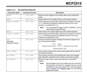
I've looked at the following messages and tried to implement the solutions, but none of the suggestions fix anything (unless I'm implementing them wrong).
1. https://devzone.nordicsemi.com/f/nordic-q-a/9353/mcp2515-with-nrf51-dk
2. https://devzone.nordicsemi.com/f/nordic-q-a/30949/how-use-nrf5-sdk14-2-0-spi-driver-functions
To me it seems like my device either has a hardware issue and won't/cannot respond or the SPI implementation for reading back is incorrect. The one thing that leads me to think this I when I use the oscilloscope I cannot see anything on the MISO line.
Based on all of the above information. Is there anything wrong that I'm doing when utilizing SPI? Or does it look like anything with the hardware is wrong? Does anyone have anything that might help me figure this out?
Thanks!

