This post is older than 2 years and might not be relevant anymore
More Info: Consider searching for newer posts

nrf52832 hangs in non-debug mode

We have custom developed board using nrf52832. When I run the example program developed in SDK15.0.0 with Soft device S132 V6.1.1, no issue noticed in running debug mode (with J-link Debugger) or non-debug mode.

 If we run the already developed code in SDK14.2.0 with soft device S132 V5.0.0, I didn’t see any issue on debug mode. As expected, peripherals are working and BLE communication started and sending data. Same setup, run in non-debug mode, noticed that it hangs on the while loop. Please advise any reason for this issue

Parents
  • hangs on the while loop

    What "while loop" ?

    When you say "debug mode" and "non-debug mode" are you talking about different build configurations? or whether the J-Link is connected or not? or whether a debug session is active or not?

  • infinite "While loop" in the main () routine. After initialization, it’s enter into the infinite while loop. Basically it checks the key press interrupt, if key pressed start advertising before go to low power mode in the  while loop.

    “ Debug Mode” : J-link is connected to Segger Embedded Studio IDE and run the program in debug mode.

    “Non Debug mode”: With out J-link connection. I tried different build configuration (release  & debug) as well. Also, checked with 32.768kHz external Xtal on the board and with out external Xtal (Configured internal RC). 

    Example program developed in SDK15.0.0 with Soft device S132 V6.1.1, no issue noticed in debug & non- debug mode. I am able to scan the BLE device from "nrfConnect" apps from my phone establish connection.

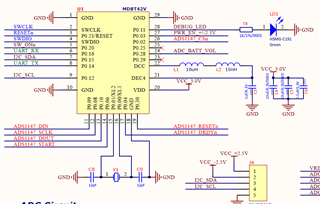
  • Are you enabling the DCDC regulator in your old code by any chance? This could potentially explain the difference between debug and non-debug mode in your case. The chip will always use the LDO regulator when in debug mode, while it's FW dependent when you exit it.  In that case, maybe you are missing the two extra inductors required for DCDC operation?

  • Thank you Vidar Beng for your response.

    DCDC regulator is not enabled in our code: Only noticed in "sdk_Congif.h"  but it's not enabled.

    // <q> POWER_CONFIG_DEFAULT_DCDCEN  - The default configuration of main DCDC regulator
     
    // <i> This settings means only that components for DCDC regulator are installed and it can be enabled.
    #ifndef POWER_CONFIG_DEFAULT_DCDCEN
    #define POWER_CONFIG_DEFAULT_DCDCEN 0
    #endif
    // <q> POWER_CONFIG_DEFAULT_DCDCENHV  - The default configuration of High Voltage DCDC regulator
     
    // <i> This settings means only that components for DCDC regulator are installed and it can be enabled.
    #ifndef POWER_CONFIG_DEFAULT_DCDCENHV
    #define POWER_CONFIG_DEFAULT_DCDCENHV 0
    #endif
    2 extra inductors (15uH & 15nH) are used in our board as Raytac's MDBT42 V P 512K V2 reference design.
    Our input power is 3V and well stable from the measurement.The firmware examples that we followed, I didn't notice that DCDC is enabled in the firmware. Please advise what circumference, DCDC is need to enable?
  • I enable the  DCDC in "sdk_config.h" and noticed that 1.265V @ DCC4 pin. 

Reply Children
  • 1. I enable the  DCDC in "sdk_config.h" and noticed that 1.265V @ DCC4 pin. Issue still exist. 1.265V Voltage at "DEC4" pin is acceptable level?

    2. One more suspect, before entering the while loop, we  call "nrf_drv_timer_ms_to_ticks" as below. When I include the test code to turn On/Off LED before and after this call, I noticed it doesn't work as expect. Not sure, this is the root cause. Please advise.

      /*Get Timer u32Ticks to provide 1sec transmission via BLE */
      u32PowerTicks = nrf_drv_timer_ms_to_ticks(&gstPOWER_TIMER, 1000);

      nrf_delay_ms(2000); 
     
     
      while(true)
      {
            /* Check button pressed or not */
        u32ErrCode = handle_push_button_functionality(&bStartAdvertise);
        if(NRF_SUCCESS != u32ErrCode)

    Any help is much appreciated.

    Thank You.

  • Ok, it doesn't appear to be related to the DCDC regulator. I was just trying to think of reasons as to why it only works in debug mode. 

    DevenE said:
    One more suspect, before entering the while loop, we  call "nrf_drv_timer_ms_to_ticks" as below. When I include the test code to turn On/Off LED before and after this call, I noticed it doesn't work as expect. Not sure, this is the root cause. Please advise.

     Does the LED blink at all? nrf_drv_timer_ms_to_ticks() is only used to convert time in ms to timer 'ticks', it won't start your gstPOWER_TIMER instance

  • Hi Vidar Berg,

    Thanks for your clarification.  LED is toggle one time only inside the “while” loop” and after first iteration, it hangs.

     Further debug on this issue, I noticed that end of the first iteration on the “while” loop,  it’s entered in to the low power mode. After that, it cannot be waked up by key press interrupt or Power timer interrupt (1 Sec. power timer) from our code. In the low power mode, we expect to be in the System ON, Full RAM retention, Wake on any event”.

    In order to enter in low power mode “sd_app_evt_wait()” function is called originally in our code. When I change this to “__WFE()”,  I couldn’t noticed any hang issue on “while” loop on non-debug mode.

    Could you please advise possible root cause for this behaviour?  We suppose to have ultra-low power mode when the instrument is idle in order to save power.

  • sd_app_evt_wait() and __WFE() has the same effect, but  the Softdevice must be enabled before you can use sd_app_evt_wait(). The function which initializes and enables the Softdevice is usually named 'ble_stack_init()' in our code examples.   

Related