This post is older than 2 years and might not be relevant anymore
More Info: Consider searching for newer posts

nRF52832 Antenna matching circuit

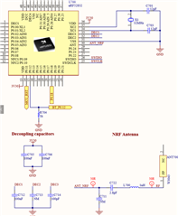
I am developing a PCB that contains this schematic, I can run the sw code on the nrf52832 and use the pinout, but I can't connect to nrf52832 via ble communication. I think the problem is in the matching circuit and I don't know what's wrong; Can you help me ?
Parents
  • The matching network is missing from your design. See the reference schematic, C3 and L1. Without these, you will have less output power and sensitivity and too much harmonics, so you will fail regulatory testing. But you should still be able to communicate so the problem is somewhere else. 

    What's the CL value of the 32 MHz crystal you're using? The formula for the load caps (C701 and C703) is Ccap = CL * 2 -Cpin, where Cpin = 4pF. For a crystal with CL = 8 pF, you must use 12 pF load caps. 

    Also note that most of the SW examples are using the 32 kHz crystal oscillator, so if you don't have this on your board, you must set the 32 kHz clock source to be the RC oscillator.

Reply
  • The matching network is missing from your design. See the reference schematic, C3 and L1. Without these, you will have less output power and sensitivity and too much harmonics, so you will fail regulatory testing. But you should still be able to communicate so the problem is somewhere else. 

    What's the CL value of the 32 MHz crystal you're using? The formula for the load caps (C701 and C703) is Ccap = CL * 2 -Cpin, where Cpin = 4pF. For a crystal with CL = 8 pF, you must use 12 pF load caps. 

    Also note that most of the SW examples are using the 32 kHz crystal oscillator, so if you don't have this on your board, you must set the 32 kHz clock source to be the RC oscillator.

Children
No Data
Related