Beware that this post is related to an SDK in maintenance mode
More Info: Consider nRF Connect SDK for new designs
This post is older than 2 years and might not be relevant anymore
More Info: Consider searching for newer posts

nrf_pwr_mgmt_run() crashes LDO on custom board?

I've been running into an issue when running examples from SDK 15.2 (S132 6.1.0) on a custom board that uses a Fanstel BC832 (uses 52832 soc) module.

At the moment I have not attached a lipo battery, and am only powering the board with a micro USB, which is regulated down to 3.3 volts.

I can flash any application without the function idle_state_handle(), which in turn calls nrf_pwr_mgmt_run().

Without calling this function, I have run multiple SDK examples, and never had any issues. When measuring voltage at the VDD pin on the module after flashing, I get a constant 3.3v, which is to be expected. The board advertises, and is connectable; no problems.

As soon as I un-comment idle_state_handle(), and re-flash the board, I will usually measure somewhere between 3.8-3.9v at the VDD pin while the board is running the firmware.

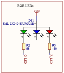
What's odd is that whenever I enable one of the LED's (I have one RGB LED), the voltage will immediately return to 3.3v. It doesn't matter which LED i turn on; using nrf_gpio_pin_clear(G_LED), turns on the LED and the voltage flips to 3.3 as long as the LED is on. As soon as i set the pin (turn off LED), the voltage will return back to around 3.9V.

I don't understand what could be going on. As a side note, I am using Segger to flash the board with SWD. The board will only advertise, when I choose Build and Debug, not when I use Build and Run. The same thing with, NRFGO studio; I flash successfully, yet the board won't advertise the application i just flashed. I am forced to Build and debug in Segger. Don't know if this has some kind of correlation.

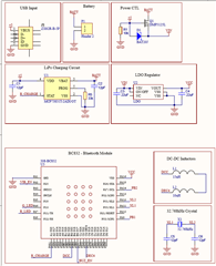
Here are the schematics. I left out the vibration motor, buzzer, and buttons, as they are irrelevant. I haven't yet defined their pins in firmware. The blue LED is not connected.

All I have defined is LED1 as pin 11, and LED2 as pin 13, Like this:

#ifndef PCA10040_H
#define PCA10040_H

#ifdef __cplusplus
extern "C" {
#endif

#include "nrf_gpio.h"

// LEDs definitions for PCA10040
#define LEDS_NUMBER    2

#define LED_1          13
#define LED_2          11

#define LEDS_ACTIVE_STATE 0

#define LEDS_INV_MASK  LEDS_MASK

#define LEDS_LIST { LED_1, LED_2 }

#define BSP_LED_0      LED_1
#define BSP_LED_1      LED_2

#define BUTTONS_NUMBER 0

I haven't yet tested the DC DC converter.

Please let me know what could be happening.

Again to be short:

  • Flash board without idle_state_handle() ..... Board functions and advertises; Voltage will always remain at 3.3v, regardless if any LED is on or off
  • Flash board WITH idle_state_handle() ....... Board functions and advertises, yet Voltage will remain at ~3.8v until an LED is turned on using CLEAR. And as soon is that LED turns off, the voltage will return to the original ~3.8v
  • Can only flash board using Build and Debug in Segger, not Build and Run. The flash will succeed, but it won't advertise after the flash. Don't know if this is relevant though.
  • There's definitely something wrong with your power supply.

    Do you have specs for D1, Q1, LDO, and LIPO charger?

    • D1STMicroelectronics - BAT20JFILM  - D1 (Digikey)
      • Diode Type Schottky
        Voltage - DC Reverse (Vr) (Max) 23V
        Current - Average Rectified (Io) 1A
        Voltage - Forward (Vf) (Max) @ If 620mV @ 1A
        Speed Fast Recovery =< 500ns, > 200mA (Io)
        Current - Reverse Leakage @ Vr 12µA @ 15V
        Capacitance @ Vr, F 30pF @ 5V, 1MHz
        Mounting Type Surface Mount
    • Q1 -  Diodes Incorporated - DMP3125L-7 - Q1 (Digikey)
      • FET Type P-Channel
        Technology MOSFET (Metal Oxide)
        Drain to Source Voltage (Vdss) 30V
        Current - Continuous Drain (Id) @ 25°C 2.5A (Ta)
        Drive Voltage (Max Rds On, Min Rds On) 4.5V, 10V
        Rds On (Max) @ Id, Vgs 95mOhm @ 3.8A, 10V
        Vgs(th) (Max) @ Id 2.1V @ 250µA
        Gate Charge (Qg) (Max) @ Vgs 3.1nC @ 4.5V
        Vgs (Max) ±20V
        Input Capacitance (Ciss) (Max) @ Vds 254pF @ 25V
        FET Feature -
        Power Dissipation (Max) 650mW (Ta)
        Operating Temperature -55°C ~ 150°C (TJ)
        Mounting Type Surface Mount
    • LDO -  ABLIC U.S.A. Inc. - S-1200B33-A6T1U - LDO (Digikey)
      • Output Configuration Positive
        Output Type Fixed
        Number of Regulators 1
        Voltage - Input (Max) 10V
        Voltage - Output (Min/Fixed) 3.3V
        Voltage - Output (Max) -
        Voltage Dropout (Max) 0.19V @ 100mA
        Current - Output 150mA
        Current - Quiescent (Iq) 1µA
        Current - Supply (Max) 40µA
        PSRR 65dB (1kHz)
        Control Features Enable
        Protection Features Over Current
        Operating Temperature -40°C ~ 85°C (TA)
        Mounting Type Surface Mount
    • Lipo -  Microchip Technology -  MCP73831T-2ACI/OT - Lipo (Digikey)
      • Battery Chemistry Lithium Ion/Polymer
        Number of Cells 1
        Current - Charging Constant - Programmable
        Programmable Features Current
        Fault Protection Over Voltage
        Charge Current - Max 500mA
        Battery Pack Voltage 4.2V
        Voltage - Supply (Max) 6V
        Interface -
        Operating Temperature -40°C ~ 85°C (TA)
        Mounting Type Surface Mount
  • Any quick thoughts/possibilities as to how a stable 3.3v could jump to 3.8-3.9 when entering low power/WFE? And return to 3.3 whenever an LED is turned on?

  • I really don't think it's the nRF52832, it can't increase the voltage in VDD. 

    My best bet is that your LDO does not play nice with the zener-diode supplying it, getting into oscillations that negatively affect the LDO's feedback loop. Do you have a scope of the LDO's input and output when the issue occurs?

    Try adding capacitance to either the input or output of the LDO.

  • Figured it out, D1 was reversed. Sorry for the confusion

Related