This post is older than 2 years and might not be relevant anymore
More Info: Consider searching for newer posts

High current consumption (4uA) even without peripherals enabled in idle

We're developing a low power communication stack, where every uA counts.

Currently, I have the system running at a few uA higher than expected, which I'm trying to track down, by disabling one part of the system at the time, and I have got to the bare minimum, which means nothing, and still get about 4uA in average current consumption.

The setup is as follows:

  • One nRF52840 (marking: N52840 QIAAC0 1816AU)
  • MBR active, no Softdevice (our ISR vector is placed at 0x1000)
  • running nRF5_SDK_15.2.0_9412b96 (well... only SystemInit and MBR from that SDK)

For most part, I've measured on our own module,  but I have also tested on a nRF52840dk, cutting the jumpers:

  • SB51-SB57 (for connection to programmer)
  • SB20-SB24 (for connection to QSPI flash)
  • SB40-SB41 (to current measurement)
  • Power into Ext supply -, P22 positive (same trace as TP24)

I have seen the same behaviour on the modified DK, but have no logs for the current that test though...

I ran two tests to mention here:

  1. Test one
    1. pass thorugh MBR reset handler to application reset handler
    2. clear BSS
    3. execute SystemInit
    4. infinite loop with "WFE" instruction
  2. Test two
    1. pass through MBR reset handler to application reset handler
    2. clear BSS
    3. skip SystemInit
    4. infinite loop with "WFE" instruction

I've verified with debugger with single stepping instrucitons in both of above cases and verified that no peripherals is touched (except from within SystemInit)

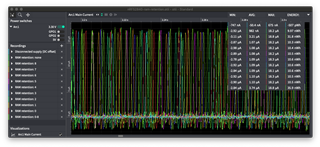
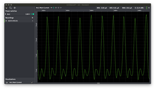
The result I get is that the average current consumption is 4.01uA, measured with an Otii by QoiTech, with all other signals disconnected. However, the current is pulsed, with about 0uA current consumption most of the time, and pulsed with a peak of about 18uA in cycles of about 4.6ms.

I have also disconnected all wires and power cycled the nRF before measuring, to verify no perpherals isn't properly reset.

I don't expect any peripherals to be running, and I think I've seen lower current consumption previously, at least on the nRF52832 in idle.

I would expect below 1uA since to timers are running, and still below, possibly about 1uA when 32kHz crystal is running.

What should I expect?

Is there any mode/state that I need to trigger to reduce the power consumption in idle?
  • Hi Max, 

    the typical sleep currents for the nRF52840 is listed under Power and clock management > Current consumption > Electrical specification > Sleep in the nRF52840 Product Specification. 

    So judging from your test cases, the applicable table entries would be:

    System ON

    Symbol Description Min. Typ. Max. Units
    ION_RAMOFF_EVENT

    System ON, no RAM retention, wake on any event

    0.97 µA
    ION_RAMON_EVENT

    System ON, full 256 kB RAM retention, wake on any event

    2.35 µA
    ION_RAMOFF_RTC

    System ON, no RAM retention, wake on RTC (running from LFRC clock)

    1.50 µA
    ION_RAMON_RTC

    System ON, full 256 kB RAM retention, wake on RTC (running from LFRC clock)

    3.16 µA

    System OFF

    Symbol Description Min. Typ. Max. Units
    IOFF_RAMOFF_RESET

    System OFF, no RAM retention, wake on reset

    0.40 µA
    IOFF_RAMON_RESET

    System OFF, full 256 kB RAM retention, wake on reset

    1.86 µA

    So unless you have explicitly configured the RAM blocks to turn off in System ON mode using the RAM[n].POWER register then you should see a current consumption around 2.35uA without the LFCLK running. WIth the LFCLK running then you should see something around 3.16uA. Note that these are typical values, i.e. mean values, one should expect deviations from this. 


    The result I get is that the average current consumption is 4.01uA, measured with an Otii by QoiTech, with all other signals disconnected. However, the current is pulsed, with about 0uA current consumption most of the time, and pulsed with a peak of about 18uA in cycles of about 4.6ms.

    The spikes you are seeing is the regulators on the NRF52840 in refresh mode. Refresh mode works by charging up internal caps regularly to provide power to the chip. So the spikes you see is the inrush current to the caps. See https://devzone.nordicsemi.com/f/nordic-q-a/14210/current-spikes-when-dcdc-is-on/54282#54282

    Best regards

    Bjørn

  • I've double checked on the same board that RAM retention affects, so it's definatly on the right track.

    I ran the following code: (only two function calls down, to simplify my build, but no interaction with peripherals)

        NRF_POWER->RAM[0].POWERCLR = 0xffffffff;
        NRF_POWER->RAM[1].POWERCLR = 0xffffffff;
        NRF_POWER->RAM[2].POWERCLR = 0xffffffff;
        NRF_POWER->RAM[3].POWERCLR = 0xffffffff;
        NRF_POWER->RAM[4].POWERCLR = 0xffffffff;
        NRF_POWER->RAM[5].POWERCLR = 0xffffffff;
        NRF_POWER->RAM[6].POWERCLR = 0xffffffff;
        NRF_POWER->RAM[7].POWERCLR = 0xffffffff;
        NRF_POWER->RAM[8].POWERCLR = 0xffffffff;
        
        while(1) {
            asm volatile ("wfe");
        }

    And commented out one line at a time to enable the bank.

    My result for no RAM retention matched the I_ON_RAMOFF_EVENT pretty closely, at 982nA.

    However, all RAM blocks enabled gives this time 3.74uA, which is 7% off from my previous measurement. However, this time, I made a more controlled measurement, and a couple of nA is definatly out of this measurements resolution.

    I am however concerned about the I_ON_RAMON_EVENT current, since the datasheet specifies 2.35uA, and my measurements is 60% higher, which practically would give at least a year difference in battery life.

    I agree that it's the typical value, but what are the tolerances that I can expect? What is the variataion between chips that you have seen? Since we should in many cases also plan for worst case.

    I attach a screenshot of the measurement, including a measurement of no connection, to verify DC offset. I will verify with a resistor to verify potential gain error in the equipment.


    Also, the banks takes differnt current, what is the expected current consumption per bank? And where can I find the mapping between bank and addresses?

  • Max Sikström said:

    I agree that it's the typical value, but what are the tolerances that I can expect? What is the variataion between chips that you have seen? Since we should in many cases also plan for worst case.

    I will try to get hold of the standard deviation data from our production tests.

    Max Sikström said:
    Also, the banks takes differnt current, what is the expected current consumption per bank? And where can I find the mapping between bank and addresses?

     I beleive the AHB Slave number shown in the Memory section , corresponds to the n in the RAM[n].POWER (n=0..8) registers. As for the current consumption per RAM block I am a bit unsure as the last block is much larger than the others. Will have to check this.

  • Thanks!

    A follow up question then on that diagram. It sounds reasonable that the RAM0 to RAM8 is the same as referred to in the NRF_POWER->RAM[n] slave, but the NRF_POWER->RAM[n].POWER and RETENTION has 16 bits refering to sections, however the diagram refers to two sections per slave for RAM0-RAM7, and 6 sections for RAM8.

    How does the sections map with the control bits? Are there any mapping, or should I enable/disable the slaves as a whole?

  • Hi Max, 

    I sincerly apologize for the late reply, I have been out of office.

    In the RAM[0-7] registers only bits 0 and 1 are used, i.e. bit 0 for section 0 and bit 1 for section 1. The rest are do not care. Each section maps to a 4kB block. 
    In RAM[8] bits 0-5 are used and each bit corresponds to a 32kB block. 

    Best regards

    Bjørn 

Related