We're developing a low power communication stack, where every uA counts.
Currently, I have the system running at a few uA higher than expected, which I'm trying to track down, by disabling one part of the system at the time, and I have got to the bare minimum, which means nothing, and still get about 4uA in average current consumption.
The setup is as follows:
- One nRF52840 (marking: N52840 QIAAC0 1816AU)
- MBR active, no Softdevice (our ISR vector is placed at 0x1000)
- running nRF5_SDK_15.2.0_9412b96 (well... only SystemInit and MBR from that SDK)
For most part, I've measured on our own module, but I have also tested on a nRF52840dk, cutting the jumpers:
- SB51-SB57 (for connection to programmer)
- SB20-SB24 (for connection to QSPI flash)
- SB40-SB41 (to current measurement)
- Power into Ext supply -, P22 positive (same trace as TP24)
I have seen the same behaviour on the modified DK, but have no logs for the current that test though...
I ran two tests to mention here:
- Test one
- pass thorugh MBR reset handler to application reset handler
- clear BSS
- execute SystemInit
- infinite loop with "WFE" instruction
- Test two
- pass through MBR reset handler to application reset handler
- clear BSS
- skip SystemInit
- infinite loop with "WFE" instruction
I've verified with debugger with single stepping instrucitons in both of above cases and verified that no peripherals is touched (except from within SystemInit)
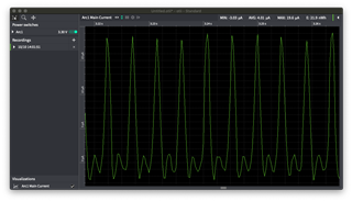
The result I get is that the average current consumption is 4.01uA, measured with an Otii by QoiTech, with all other signals disconnected. However, the current is pulsed, with about 0uA current consumption most of the time, and pulsed with a peak of about 18uA in cycles of about 4.6ms.
I have also disconnected all wires and power cycled the nRF before measuring, to verify no perpherals isn't properly reset.
I don't expect any peripherals to be running, and I think I've seen lower current consumption previously, at least on the nRF52832 in idle.
I would expect below 1uA since to timers are running, and still below, possibly about 1uA when 32kHz crystal is running.
What should I expect?
Is there any mode/state that I need to trigger to reduce the power consumption in idle?