
I need to program the nrf51 controller directly from PC. How to connect nRF51822 controller from PC through UART/SWD pins to program.
I need to program the nrf51 controller directly from PC. How to connect nRF51822 controller from PC through UART/SWD pins to program.
I need to do something similar to the above. I have a finished pulse oximeter using the nRF51822 on a YJ-14001-nrf51822 daughter board. The device is to test a new BLE protocol specification and I have been provided with the original software in a Keil project. I need to replace the existing BLE protocol with the new protocol specification.
According to the company, I can flash the software using SWD. They have given me the input soldering points on the daughter board to make the SWD connection on the Pulse OX. Now what I need to do is interface that to the PC. I have no idea how to do this.
From this discussion it appears that I cannot repurpose a USB cable and flash the device from the Keil IDE even though it supports SWD via USB when using a DK..
How do I do this directly to the nrf51822 SWD contact points? Do I need additional hardware to go from USB to SWD?
Thanks. If this is not answered in a few days (old post) I will make an additional post.

Hi,
Not sure I understand correctly, but the DK has a debugger IC on it (the one with the sticker) that translates the information received from Keil over the USB cable into SWD. Hypothetically you could direct SWD over a USB cable from the debugger to your target nRF51, the nRF51 just needs an electrical connection to the SWD, SWDIO, VDD and GND pins on the debugger.
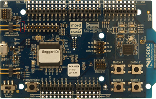
You can use P20 or P19 on the DK to program or debug an external target (instead of the nRF51 on the DK itself), see section 6.10 in the DK User Guide.
Best regards,
Andreas

I DO have the DK. My production target also has its own power (it is a real market device) but the device will not be on when flashing. So what you are saying is that I could take a USB cable connected from the PC and wire it directly to the SWD pins on my production device (I know where to solder the connections). Will there be a power problem? I've seen in this forum somewhere that the voltage needs of the nrf51822 are not that supplied by USB.
Alternatively, I could connect the USB cable to the DK and wire the P20 and P19 pins to my production device. The latter sounds easier and safer as I assume that all voltage and power supply issues are worked out.
Hi,
brianreinhold said:So what you are saying is that I could take a USB cable connected from the PC and wire it directly to the SWD pins on my production device (I know where to solder the connections)
No, the USB port on the PC will not understand the SWD protocol. You can connect the SWD pins on your debugger to SWD through an USB cable, obviously this will not work as a 'normal' USB port (e.g. by a compunter) and for that it might not be an ideal solution as the debug USB port might be confused with a normal USB port, care must be taken for this to handle the 5V bus voltage in case it is incorrectly inserted into a normal USB port.
brianreinhold said:Alternatively, I could connect the USB cable to the DK and wire the P20 and P19 pins to my production device. The latter sounds easier and safer as I assume that all voltage and power supply issues are worked out.
Yes, this would work. The interface MCU on the DK acts as a translator, and will translate the communication from the PC (over USB) into SWD which is needed by the nRF51822 target. This needs SWDCLK and SWDIO for communication, and VDD (called VTG by the debugger) and GND for reference voltage. Note that the VTG connection on the debugger does not supply the target, you must make sure to do this externally.
Best regards,
Andreas
My DK has both VDD and VTG pins. Which is the correct one to use?
Hi,
VTG is the input of the debugger, that is to be connected to VDD on the debug target. If the target is supplied and powered by its own supply/battery/etc. then this will work, if not then you can connect VDD (on the DK) to VTG (and by extension VDD on the target) to power the target. See as an example the wiring in this case.
Note that you might want to cut SB9 to not power the nRF51 on the DK itself. This can be reverted by shorting SB9, or plugging a jumper across P22:
Best regards,
Andreas
Thanks for that information. I do not know if the target is self powered when trying to flash new code. I am asking the company, but I do not believe it is. Pressing the power button triggers all kinds of sensor activity that I have no control over and has nothing to do with the BT module. So I am pretty sure I have to power the target from the DK. I assumed that I would have to wire the VDD of the DK to VDD of the target to do that. If self powered, I would use VTG of the DK to VDD of the target. But I guess it is slightly more complicated than that.
Hi,
OK, sounds like it should be fine. If the target is powered it should be fine to power it using the DK, if 1.8V it will be out of range for the debugger on the DK anyway.
Best regards,
Andreas
It turns out I can get power from the batteries on the production device. So I have used the VTG pin on P20 to connect to the VDD 'pin' on the production device. The DK user's guide mentions that P20 is for 'shield targets' but I am not sure what that means.
I also have limited equipment and tools to make the solder connections on the target board. They look okay but its hard to tell.
So now I run the Kiel IDE with the project and plug the USB cable into the DK. Yellow led comes on. I start the Start/Stop debug session on the Keil IDE and get the error 'no Cortex-M device found ...'. Now this project was provided by the developer of the production device so I figure I am using the DK wrong or have not done a solid job of soldering.