This post is older than 2 years and might not be relevant anymore
More Info: Consider searching for newer posts

Problems using TWI in slave mode

Hello,

I am using a development board pro nrf52840 mini from Sparkfun. 

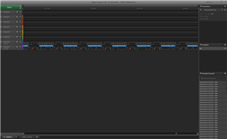
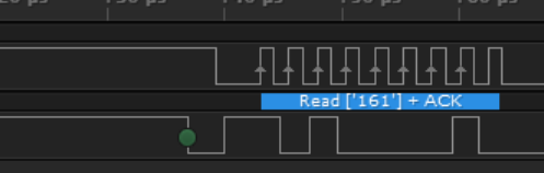
I'm trying to use the TWI peripheral on nrf52840 to communicate with an external device (another microcontroller). The nrf52840 is supposed to be a slave on TWI and the external device to be the master. I'm using the example 'nRF5_SDK_15.3.0_59ac345\examples\peripheral\twi_master_with_twis_slave\' with SCL on PIN P0.11 and SDA on PIN P0.8 and I have a problem that the slave does not respond. 

In this example, I do not know which instance of TWIS is activated and I do not find in the documentation which pins correspond to which TWIS instance.

From the external device, I scan for the TWI address in interval [1,127] and nrf52840 does not respond at any address.

Can you, please, tell me how can I modify this example code so the slave answers or can you provide an example to startup the slave and to receive data?

Thank you.

Parents
  • "In this example, I do not know which instance of TWIS is activated and I do not find in the documentation which pins correspond to which TWIS instance."

    • The TWIS instance 1 is used. Take a look at the file nRF5_SDK_15.3.0_59ac345\examples\peripheral\twi_master_with_twis_slave\eeprom_simulator.c on line 91
    • The slave SCL corresponds to pin 31 and the slave SDA corresponds to pin 30. Take a look at the file nRF5_SDK_15.3.0_59ac345\examples\peripheral\twi_master_with_twis_slave\config.h on line 71.

    "Can you, please, tell me how can I modify this example code so the slave answers or can you provide an example to startup the slave and to receive data?"

    Study the file eeprom_simulator.c and try to understand how it works, then modify it according to your slave. If you have any particular questions, please ask.

    You could also follow the guide on the infocenter, as an initial step to get an understanding of how it works.

    Best regards,

    Simon

Reply
  • "In this example, I do not know which instance of TWIS is activated and I do not find in the documentation which pins correspond to which TWIS instance."

    • The TWIS instance 1 is used. Take a look at the file nRF5_SDK_15.3.0_59ac345\examples\peripheral\twi_master_with_twis_slave\eeprom_simulator.c on line 91
    • The slave SCL corresponds to pin 31 and the slave SDA corresponds to pin 30. Take a look at the file nRF5_SDK_15.3.0_59ac345\examples\peripheral\twi_master_with_twis_slave\config.h on line 71.

    "Can you, please, tell me how can I modify this example code so the slave answers or can you provide an example to startup the slave and to receive data?"

    Study the file eeprom_simulator.c and try to understand how it works, then modify it according to your slave. If you have any particular questions, please ask.

    You could also follow the guide on the infocenter, as an initial step to get an understanding of how it works.

    Best regards,

    Simon

Children
  • Thank you for your answer, but unfortunately the nrf52840 (slave) does not respond to the external device (master).

    I made your changes, but no result. I also modified the \nRF5\nRF5_SDK_15.3.0_59ac345\examples\peripheral\twi_master_with_twis_slave\sparkfun_nrf52840_mini\blank\config\sdk_config.h file. The changes I've done are the following:

    #define NRFX_TWIM_ENABLED 0
    #define NRFX_TWIS1_ENABLED 1
    #define NRFX_TWI1_ENABLED 1

    The only thing modified in \nRF5\nRF5_SDK_15.3.0_59ac345\examples\peripheral\twi_master_with_twis_slave\main.c is to comment the following lines, because I want nrf52840 to be the slave :

        // err_code = twi_master_init();
        // APP_ERROR_CHECK(err_code);
    Have these changes any impact on the behaviour of the slave?
    How can I find out the TWI address of the nrf52840? The device does not respond if I scan it in the interval [1,127].
    Moreover, if I run the original example \nRF5\nRF5_SDK_15.3.0_59ac345\examples\peripheral\twi_master_with_twis_slave, I observed that a periodic reset is issued. I think it's a period reset because the blue middle led is blinking on the board.
     
    Thank you.
  • Do you have a logic analyzer? If you have, attach it to the SDA and SCL lines and provide the result here. If you don't have one, I will try to see if I can do it myself.

    Best regards,

    Simon

  • The search is done between [0x00, 0xFA] and for all, the result is NAK.

  • I was able to make this work. First I added the following lines of code to the twi_master_with_twis_slave in the main() function (right before while(1)):

    err_code = nrf_drv_twi_rx(&m_twi_master, EEPROM_SIM_ADDR, test_buff, IN_LINE_PRINT_CNT);
    if(err_code == NRF_SUCCESS)
    {
        NRF_LOG_RAW_INFO("TWI device detected \n");
    } else{
        NRF_LOG_RAW_INFO("TWI device NOT detected \n");
    }

    Then I shorted the following pins:

    • TWI_SCL_M (P0.03) - EEPROM_SIM_SCL_S (P0.31)
    • TWI_SDA_M (P0.04) - EEPROM_SIM_SDA_S (P0.30)

    I built and flashed the example, and observed that "TWI device detected" appeared in the terminal.


    Then I did the following:

    • Flashed the modified twi_master_with_twis_slave example onto two different nRF52832 DK's
    • Made sure the devices had common ground by connection GND from one of the boards to GND on the other board
    • Decide which board should be the master and which board should be the slave (doesn't matter which board you choose to be slave/master)
    • Connect P0.03 on the master to P0.31 on the slave
    • Connect P0.04 on the master to P0.30 on the slave
    • Reset the slave board first and the master board after (the order is important)
    • Check that "TWI device detected" appeared in the terminal of the master board

    I checked the signals in a logic analyzer as well and saw that the address was ACKed (If you discard the last binary value from 0d161, you will get 0x50=EEPROM_SIM_ADDR):

    Here is the modified project in zipped format: twi_master_with_twis_slave.zip

    Best regards,

    Simon

  • Thank you very much, but I tried with your first example (to shorten the pins of the same board) and SCL and SDA lines are down all the time. I analyzed RESET pin and it's ok, even if the blue led is blinking continuously (is this blink normal?).

    Which soft are you using to see NRF_LOG messages?

    Are you using sparkfun nrf52840 mini or another board?

Related