This post is older than 2 years and might not be relevant anymore
More Info: Consider searching for newer posts

new to nrf52 and cant start PWM as show in datasheet example

Hello,

I've got a nrf52840 DK and Adafruit nrf52840 Express (less complicated then DK) i'm trying to run a PWM example from datasheet (46 PWM — Pulse width modulation page 556-557). So the code 

uint16_t pwm_seq[4] = {PWM_CH0_DUTY, PWM_CH1_DUTY, PWM_CH2_DUTY, PWM_CH3_DUTY};
NRF_PWM0->PSEL.OUT[0] = (first_pin << PWM_PSEL_OUT_PIN_Pos) | (PWM_PSEL_OUT_CONNECT_Connected <<PWM_PSEL_OUT_CONNECT_Pos);
NRF_PWM0->PSEL.OUT[1] = (second_pin << PWM_PSEL_OUT_PIN_Pos) |(PWM_PSEL_OUT_CONNECT_Connected <<PWM_PSEL_OUT_CONNECT_Pos);
NRF_PWM0->ENABLE = (PWM_ENABLE_ENABLE_Enabled << PWM_ENABLE_ENABLE_Pos);
NRF_PWM0->MODE = (PWM_MODE_UPDOWN_Up << PWM_MODE_UPDOWN_Pos);
NRF_PWM0->PRESCALER = (PWM_PRESCALER_PRESCALER_DIV_1 <<PWM_PRESCALER_PRESCALER_Pos);
NRF_PWM0->COUNTERTOP = (16000 << PWM_COUNTERTOP_COUNTERTOP_Pos); //1 msec
NRF_PWM0->LOOP = (PWM_LOOP_CNT_Disabled << PWM_LOOP_CNT_Pos);
NRF_PWM0->DECODER = (PWM_DECODER_LOAD_Individual << PWM_DECODER_LOAD_Pos) |(PWM_DECODER_MODE_RefreshCount << PWM_DECODER_MODE_Pos);
NRF_PWM0->SEQ[0].PTR = ((uint32_t)(pwm_seq) << PWM_SEQ_PTR_PTR_Pos);
NRF_PWM0->SEQ[0].CNT = ((sizeof(pwm_seq) / sizeof(uint16_t)) <<PWM_SEQ_CNT_CNT_Pos);
NRF_PWM0->SEQ[0].REFRESH = 0;
NRF_PWM0->SEQ[0].ENDDELAY = 0;
NRF_PWM0->TASKS_SEQSTART[0] = 1;

im uploading this code with an Arduino IDE and Adafruit Arduino Support Setup (it compiles, uploads and everything seems to be okay). But i cant get any PWM. There are 2 LEDs (Adafruit nrf52840 Express), 1 is on pin P1.15 wich i am tryng to use as PWM indicator. 

So I have a few questions:

PWM_CHx_DUTY is a duty cycle of a PWM and why are there 4 duty cycles?

first_pin (second pin) is just a number of pin? for example, ih LED is connected to P1.15, should i just define first_pin = 15? Because it doesnt seems to work.

Wasky

Parents
  • Hi

    Doesn't Arduino provide it's own PWM API so you don't have to implement it from scratch?

    In general we don't support non Nordic kits (one advantage of using the DK), but generic questions we can obviously answer. 

    PWM_CHx_DUTY is a duty cycle of a PWM and why are there 4 duty cycles?

    Each PWM module supports up to 4 output channels. Each of these channels will share frequency and phase, but have individual duty cycle control, and an individual invert setting allowing you to invert the output. 

    first_pin (second pin) is just a number of pin? for example, ih LED is connected to P1.15, should i just define first_pin = 15? Because it doesnt seems to work.

    Setting the pin to 15 enables P0.15, not P1.15. To use port 1 you have to add 32 to the pin number, so that first_pin should be assigned (32 + 15), or 47

    Best regards
    Torbjørn

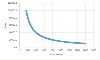
  • Thanks for Your reply, I have figured out with PINs. DK seems to be ok, but SEGGER is a bit more complicated (tbh it’s very complicated when you switch from Arduino IDE to SEGGER) and I have problem with adding libraries to SEGGER. Also cant fully understand which of them I need, basically what I’m trying to do, is run PWM on 2 pins with ~50% duty cycle (a bit less because need a dead time around 130us) and be able to change frequency in range 10kHz-100kHz, which is controlled by potentiometer. After failing to set up SAADC I got an Ad fruit nrf52 express, because it’s possible to use it with Arduino IDE and use simple functions such as analogRead(), but I have also failed to understand how {PWM_CH0_DUTY, PWM_CH1_DUTY, PWM_CH2_DUTY, PWM_CH3_DUTY}; works (sitting with oscilloscope and changing things doesn’t gave any result)

    So yeah, I’m kind of stuck between nrf52 DK and Adafruit nrf52

Reply
  • Thanks for Your reply, I have figured out with PINs. DK seems to be ok, but SEGGER is a bit more complicated (tbh it’s very complicated when you switch from Arduino IDE to SEGGER) and I have problem with adding libraries to SEGGER. Also cant fully understand which of them I need, basically what I’m trying to do, is run PWM on 2 pins with ~50% duty cycle (a bit less because need a dead time around 130us) and be able to change frequency in range 10kHz-100kHz, which is controlled by potentiometer. After failing to set up SAADC I got an Ad fruit nrf52 express, because it’s possible to use it with Arduino IDE and use simple functions such as analogRead(), but I have also failed to understand how {PWM_CH0_DUTY, PWM_CH1_DUTY, PWM_CH2_DUTY, PWM_CH3_DUTY}; works (sitting with oscilloscope and changing things doesn’t gave any result)

    So yeah, I’m kind of stuck between nrf52 DK and Adafruit nrf52

Children
Related