This post is older than 2 years and might not be relevant anymore
More Info: Consider searching for newer posts

Extendability of the Nordic Thingy:52?

Hey,

Up until now I have only been dealing with software. Now however, I want to create a device that I can use to track my bike by GPS and heading. In the future, I want to act given certain light conditions, like turn a light on when it becomes dark.

So to me, it seems like the Thingy52 will make all this possible? But .. what I don't get is how does the T52 actually make things happen? It has a lot of sensors, but .. how can I use this data to turn on an external light? I would prefer that the lights dim in and out, so I can't use a simple electrical relay..

I assume I'll need to connect additional things to the T52? But can this be done?

Any and all input appreciated.

Thanks! 

Parents
  • Hello,

    Do you mean Thingy:52 or Thingy:91? The latter is the one with GPS and LTE modem. 

    Kind regards,
    Øyvind

  • Thanks for your reply, and sorry, I should have included both.

    As far as I understand: I'll assume that the gyro on the Thingy:52 can be used to obtain compass heading while motionless?

    So I believe I'll need the T52 for heading and the Thingy:91 for GPS tracking (which uses LTE-M to update backend). Is this correct?

    I get a sneaking feeling that I may be better off with some other hardware..

    Johan

  • Why indeed :-)

    Well, the final product will probably have almost all the features of T52 combined with the GPS and LTE-M from T91. However, for the MVP we plan only on using the gyro from T52.. Down the line we plan to use almost every other feature as well.

    With no experience in this field, I wasn't really able to tell by looking at the PCB if any of the Thingy's can be extended. So how or where is the interface to hook up external modules?

    Also, I was a bit disappointed to read that the speaker (which also wasn't indicated on the PCB overview in the PDF of the T52) reduces the precision of the compass. We don't need the speaker.. Can I simply ... remove it from the board?

    I really appreciate your input Øyvind. Jeg antar du også er norsk? Takk for hjelp så langt.

  • Hei igjen Johan Slight smile

    Norsk her, ja. Sittende på hovedkontoret vårt i Trondheim. Men fortsetter samtale på engelsk, da dette er en public ticket Slight smile

    JohanHWB said:
    With no experience in this field, I wasn't really able to tell by looking at the PCB if any of the Thingy's can be extended. So how or where is the interface to hook up external modules?

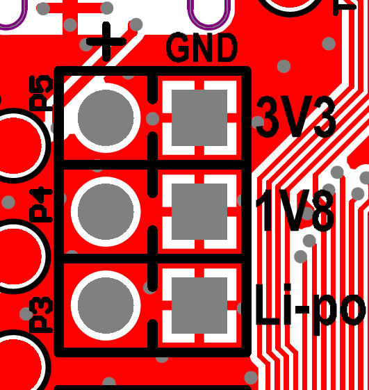
     I could have been more specific with regards to that. The Thingy:91 documentation has more information about the topic. The Pin Map chapter shows which pins are spare, e.g. SPARE1 = P0.06 - Digital GPIO externally available. Note that the spare pins are connected to the board controller nRF52840. While the available connectors on the board are described in the Connectors chapter

    In Connector Pinouts, we see that P6 has spare pins 1 to 6. A more detailed overview can be also found in the Hardware description files found on the Thingy:91 download page, this includes schematics and layout in pdf format: PCA20035_Schematic_And_PCB.pdf
     

    JohanHWB said:
    Also, I was a bit disappointed to read that the speaker (which also wasn't indicated on the PCB overview in the PDF of the T52) reduces the precision of the compass. We don't need the speaker.. Can I simply ... remove it from the board?

    Removing the speaker or any other part by desoldering might be more timeconsuming if you are not experienced with HW, I would recommend getting an external module with gyro/compass e.g. the SEN-13762 from SparkFun. This will also add more functionality to the Thingy:91 with Gyroscope, (an extra) Accelerometer and Magnetometer (compass), along with the sensors already on the board i.e. color sensor and Pressure, Humidity, Temperature and Gas sensor

    And not to forget that the Thingy:91 already has an Asset Tracker application.

    Hopes this answers more of your questions!

    Kind regards, 
    Øyvind

  • Hei,

    So I got the SEN-13762 as suggested.

    Which means I'll be heading to a hackerspace to connect the two boards.

    For this .. having never done anything like this before, you say that P6 has "spare pins". All 6 are described as "GPIO of the nRF52840" - which I don't fully understand. I have never done anything like this before, so.. shouldn't at least one of the pins be "ground" or something - so there is a signal to read when combined with the other pins?

    I'm trying to figure out how to connect the two modules. Any additional pointers would be greatly appreciated.

  • Hei!

    JohanHWB said:
    I have never done anything like this before, so.. shouldn't at least one of the pins be "ground" or something - so there is a signal to read when combined with the other pins?

    Yes, all the pins are GPIO on connector P6. GND is found on P3, P4, P5, and P7. Just make sure to use the pins marked with GND or you might damage your module.


    JohanHWB said:
    I'm trying to figure out how to connect the two modules. Any additional pointers would be greatly appreciated.

     Sparkfun has a good "Hookup guide" on their page which shows how to connect your module. In your case, you could connect VDD and GND on the SEN-13762 to P5 (3V3 and GND), while SDA and SCL should be connected to two of the GPIOs on P6. You will need to configure these GPIOs as SDA and SCL. Or you can connect to TP9 (SCL) and TP10 (SDA).

  • Thanks.

    So I did as advised. Not yet tried to turn it on.

    Additionally I would have BLE. Do I get that by adding a second module?

    The nRF52840 has protocol support for Bluetooth 5, but not the actual hardware.. So now that SEN-13762 occupies the 3V3 pins (which is the voltage used by the boards I have seen so far) - how would I power the new module?

    And the data, do I use additional GPIOs to reach the nRF52840?

Reply
  • Thanks.

    So I did as advised. Not yet tried to turn it on.

    Additionally I would have BLE. Do I get that by adding a second module?

    The nRF52840 has protocol support for Bluetooth 5, but not the actual hardware.. So now that SEN-13762 occupies the 3V3 pins (which is the voltage used by the boards I have seen so far) - how would I power the new module?

    And the data, do I use additional GPIOs to reach the nRF52840?

Children
  • Also, initially I asked if anyone could help me understand how these boards actually gets things done - like turning on and off lights? How do I make things happen? Yep. Never done this before. Trying to read about these things, but everything I come across is frustratingly vague.

  • JohanHWB said:
    Additionally I would have BLE. Do I get that by adding a second module?

    The nRF52840 is a Bluetooth 5 device which supports Bluetooth Low Energy.

    JohanHWB said:
    The nRF52840 has protocol support for Bluetooth 5, but not the actual hardware

    Can you please elaborate on what you mean with not the actual HW?

    JohanHWB said:
    So now that SEN-13762 occupies the 3V3 pins (which is the voltage used by the boards I have seen so far) - how would I power the new module?

    I don't understand. What new module? 

    JohanHWB said:
    And the data, do I use additional GPIOs to reach the nRF52840?

    As the SEN-13762 communicates via TWI (I2C) you will need to connect it either GPIO pins on P6, or you can connect to TP9 and TP10. 

    JohanHWB said:
    Also, initially I asked if anyone could help me understand how these boards actually gets things done - like turning on and off lights? How do I make things happen? Yep. Never done this before. Trying to read about these things, but everything I come across is frustratingly vague.

    What do you know about HW? It is easier to point to correct documentation knowing what you know. 

    Kind regards,

    Øyvind

  • This is why it is so hard to understand how to get things done: references refer to things with different names than what the thing calls itself. Exhausting. On top of that - all articles I come across are poorly structured and confusing. Aaaahhg!
    Anyway...
    When I compare the Thingy 52 with 91 I see that Bluetooth is only listed on 52 with a colourful box. Then I read that the 91 has "support" for bluetooth. This, to me, can only mean one thing: that the 91 doesn't have the necessary hardware to establish a connection to eg. an iPhone - though it will be able to support bluetooth if added in some way.
    Following that logic, I need to add another module as 91 cannot actually by itself connect with another device using Bluetooth. I used the word "module" as I though this would be the correct term to use - you used term "external module" to describe the SEN-13762.
    Now, you make me think that the Thingy:91 does in fact support bluetooth out of the box, despite it not being listed as a feature with a colourful box?
    Btw. how do I do those cool "JohanHWB said:" quotes?

    What do you know about HW? It is easier to point to correct documentation knowing what you know.

    Well - that is easy. I know nothing.

  • I understand that it can be difficult, you have started on a difficult path with no prior knowledge of electronics. Based on this information, I recommend starting with something very basic to get you started. Perhaps some sort of "Getting Started with electronics" would be a good start as well, to learn the terminology and basic concepts i.e parallel and serial connections.

    How are you comparing the Thingy:91 to Thingy:52? How can you conclude that the Thingy:91 does not have the necessary HW to establish a BLE connection?

    An external module is something that is connected to externally and not on the board itself.

    JohanHWB said:
    Btw. how do I do those cool "JohanHWB said:" quotes?

     Mark the text and a "quote" button will appear.

  • After a quick chat with a friend, this is my current understanding:</p>

    The Thingy:91 is a programmable CPU with a number of connected sensors, and general purpose input and output pins (GPIOs). The CPU is a state machine running at a suitable clock rate. There is also a polling rate used to check the state of the sensors and GPIOs.

    I expect the clock rate to be much higher than the polling rate, to allow the CPU time to process the polled data - but more about below.

    The electric current of an external module runs from + pin to the ground pin. Data sent from it is a fraction of this power re-routed to a general purpose (input) pin.

    The simplest example would be a simple switch. To avoid short circuiting the energy source the switch is connected to a resistor. The GPIO pin taps into the power between the switch and resistor. When the switch is turned on, power runs from + through the switch, then the resistor and ends up in the ground (pin). However, the GPIO also gets some of the current, but due to the extremely high impedance of the CPU reading the GPIO, the current doesn’t fry the CPU.

    On the next cycle, the CPU checks the state of the GPIO and if there is an electric current (1) or not (0), before processing the data according to its programming. The result could be to power up a LED light on the board when the GPIO is 1.

    GPIOs are also used to communicate series of bits to and/or from external modules. Organising bits in series allows grouping of multiple sources.

    Serliaizing data means we are not limited by the number of GPIO pins on the CPU board.

    If the data is serialised the CPU processing the data needs to be able to interpret the data. For this some kind of protocol is used, which specifies a timer to be used to sequence the bits.

    I guess this protocol is specified in the code used to run the CPU, and therefore that is can be changed. I guess there are some known requirements associated with both the CPU, the sensors on the board, and the connected external modules which limit the range of these timers.

Related