This post is older than 2 years and might not be relevant anymore
More Info: Consider searching for newer posts

What should be the PINOUT numbers of the nrf52832 breakout board Please help

Hi 

   I have been working with the nrf52832 breakoutboard from sparks fun and the nrf52 10040 Dev board.

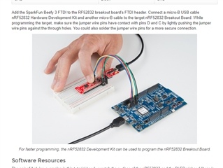
I want to work with SPI communication in order to intergrate an accelerometer LIS331HH. I tryied the SPI examples provided by the SDK it worked with the DEV board when I did a loop test but I dont know which pins I should use to test out the breakout board via the DEv kit as in to program the breakout board via the Dev board. 

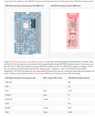
What should be my MISO, MOSI , CLK and CS pin numbers of the breakout board? Should I be using the same pinouts for SPI allocated for an arduino uno board  ? Or should I map the pins and ports of the DEv to the break out ,

In summary, I want to know the pinout numbers of the breakout  for SPI interface ? Can You direct me to a direct link where I can find this.How should I do this and how to perform the LOOPtest on the breakout 

BTW I'm using segger embedded studio to code. 

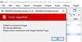
My next question is get this error report when I try to program with breakout via the dev board,what should I do for this?

Someone please please please help me. Im in a very bad condition. Thank You in advance. You people are amazing.

  • Hi! 

    For your first question, you can configure the pins however you like. There are no set GPIOS pins for SPI, or any other peripheral for that matter. If can also take a look at examples/peripheral/spi in the nRF5 SDK and check out the sdk_config.h file. This is where the pins are set, and in this example the configuration is:

    SCK is 26, MISO is 30, MOSI is 29, and SS is 31.

    For your second question, it just looks like your board isn't connected to the computer. How are you connecting the board? Is the board powered on?

    Best regards,

    Heidi

  • Hi  Thank you for your quick response,

    SCK is 26, MISO is 30, MOSI is 29, and SS is 31.

    As in this applies to the breakout board and the Dev kit  as well rite there? Since this is pin assignments are  already on the SPI example provided by the SDK?

    For your second question, it just looks like your board isn't connected to the computer. How are you connecting the board? Is the board powered on?

    For this I'm powering up the same way they have mentioned in the hookup guide for the sparks-fun breakout board  link here

    this whole thing worked for a while i even tested some of the examples and then started getting this error message  


    please help on this 

     I also am not able to test a very simple loop test for SPI  using this breakout board using arduino  can u please help or direct me a solution , I know I should be asking the arduino forum about this but they havent really replied and it is very urgent or

    else is there a way I can test the if the SPI connections of the breakout board works via  the devlopment board ?

     as a start can you help me or direct me where I could blink led on breakout via dev board using ses please ?

    it will be much help for me !! Your products are always great btw and you guys support us learners well

    Thank you!

  • Hi!


    christine_dev said:
    As in this applies to the breakout board and the Dev kit  as well rite there?

     No, sorry, I misunderstood your question. For the breakout board it looks like most pins are GPIO pins, take a look at this schematic. You can for example use P0.11, P0.12, P0.13, P0.17, which corresponds to 13, 14, 15, and 16 on the breakout board. It does not matter which pins are designated to do what, as long as you program it correctly.

    christine_dev said:
    this whole thing worked for a while i even tested some of the examples and then started getting this error message  

     This is strange. You are sure both boards are powered on and working? Could you send me a picture of your set up? 

    christine_dev said:
     I also am not able to test a very simple loop test for SPI  using this breakout board using arduino

     Could you expand on how you're testing, what the setup is, what code are you running, etc. It's hard to know why it isn't working from so little information?

    christine_dev said:
    is there a way I can test the if the SPI connections of the breakout board works via  the devlopment board

     The easiest way to test this is to use a logic analyzer. If you don't have access to that, you could also use a multimeter to check the voltage on the MISO or MOSI pins. 

    christine_dev said:
    direct me where I could blink led on breakout via dev board using ses please

     Unfortunately, since this isn't Nordic's product we have no SDK examples for this board and I can't seem to find anything online. I suggest looking through the Arduino forums, as I'm sure somebody has example code out there for this board.

Related