This post is older than 2 years and might not be relevant anymore
More Info: Consider searching for newer posts

mic input device not find

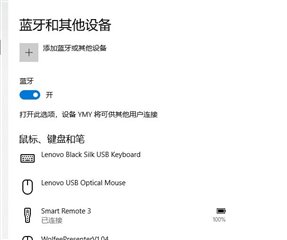
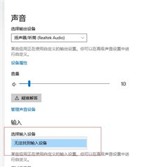
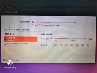
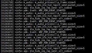
When I download \nRFready Smart Remote 3 nRF52 v1.2.1alpha\nRF5x SDK-SR3\examples\ble_peripheral\smart_remote_3_nrf52\Projects\Firmware_nRF52832 to my 52832 device, I can't find the mic input device on my computer, either Windows or Linux. What's going on here

Parents
  • For Windows, this is correct, as BLE Audio Profile is not supported in Windows on Smart Remote 3 (SM3). This information may not be clear with the quick-start guide. Only touchpad, buttons, and gyro work in Windows. Have you configured the SM3 audio for Ubuntu? Does the SM3 show in Ubuntu at all? 

    The Quick-Start guide states:
    The Product example comes with pre-installed firmware. For a quick start with this device, just insert batteries, and continue reading in Pairing with Windows (basic use) or Pairing with Ubuntu (use with audio).

    Let me know how that works.

  • When I amend the CONFIG_AUDIO_CODEC value to 3, I can find the microphone input devices on ubuntu, but the transmission of data length is wrong, I now the equipment only connect a mic, I CONFIG_PDM_MIC is 2, must meet two mic. The following figure is my pick in the ubuntu information displayed on the device and a serial port of the log, trouble to help analyze.

  • Are you using the Smart Remote 3 reference design HW or other HW?

  • Ok, then you will need to configure your hardware accordingly. Attached are two files that you need to save in the following folder: 

    nRF5x SDK-SR3\examples\ble_peripheral\smart_remote_3_nrf52\Source\Configuration
    sr3_config_nrf52832_custom.h 
    diff --git a/examples/ble_peripheral/smart_remote_3_nrf52/Source/Configuration/sr3_config_nrf52832_custom.h b/examples/ble_peripheral/smart_remote_3_nrf52/Source/Configuration/sr3_config_nrf52832_custom.h
    index ba97e42..98b9a64 100644
    --- a/examples/ble_peripheral/smart_remote_3_nrf52/Source/Configuration/sr3_config_nrf52832_custom.h
    +++ b/examples/ble_peripheral/smart_remote_3_nrf52/Source/Configuration/sr3_config_nrf52832_custom.h
    @@ -58,7 +58,7 @@
     // <e> Enable Accelerometer Support
     // <i> Enables the low power accelerometer module.
     /**@brief Accelerometer: Enable Accelerometer Support */
    -#define CONFIG_ACC_ENABLED 1
    +#define CONFIG_ACC_ENABLED 0
     
     // <o> Accelerometer driver
     // <i> Select the accelerometer driver
    @@ -151,7 +151,7 @@
     //  <3=>Opus
     //  <4=>SBC
     /**@brief Audio Codec */
    -#define CONFIG_AUDIO_CODEC 1
    +#define CONFIG_AUDIO_CODEC 3
     
     // <e> Enable Active Noise Reduction
     // <i> The Active Noise Reduction (ANR) system involves two microphones. One of them picks up the voice of the user while the other one picks up background noise.
    @@ -186,7 +186,7 @@
     //  <24000=>24 kHz
     //  <32000=>32 kHz
     /**@brief Sampling Frequency */
    -#define CONFIG_AUDIO_SAMPLING_FREQUENCY 8000
    +#define CONFIG_AUDIO_SAMPLING_FREQUENCY 16000
     
     // <h> ADPCM Options
     // <o> Audio Frame Size
    @@ -441,7 +441,7 @@
     // <q> Enable PDM Microphone Power Control
     // <i> Enable control over the microphone power line. Remember to configure a PDM Microphone Power Control Pin in the I/O Configuration.
     /**@brief Enable PDM Microphone Power Control */
    -#define CONFIG_PDM_MIC_PWR_CTRL_ENABLED 1
    +#define CONFIG_PDM_MIC_PWR_CTRL_ENABLED 0
     // </h>
     
     // <h> Bluetooth Audio Service Options
    @@ -450,12 +450,12 @@
     // <q> Audio HID Service enabled
     // <i> HID Service for audio enabled and available for audio transmission.
     /**@brief Audio HID Service enabled */
    -#define CONFIG_AUDIO_HID_ENABLED 0
    +#define CONFIG_AUDIO_HID_ENABLED 1
     
     // <e> Audio ATVV Service enabled
     // <i> ATVV Service for audio enabled and available for audio transmission.
     /**@brief Audio ATVV Service enabled */
    -#define CONFIG_AUDIO_ATVV_ENABLED 1
    +#define CONFIG_AUDIO_ATVV_ENABLED 0
     
     // <o> Remote control ID <0x00-0xFF>
     // <i> ID value used in ATVV audio frame headers.
    @@ -572,7 +572,7 @@
     // <e> Enable Buzzer
     // <i> Enable the buzzer function, which is controlled by Bluetooth Immediate Alert service.
     /**@brief Enable Buzzer */
    -#define CONFIG_BUZZER_ENABLED 1
    +#define CONFIG_BUZZER_ENABLED 0
     
     // <h> Logging Options
     // <i> This section configures module-specific logging options.
    @@ -600,7 +600,7 @@
     // <e> Enable DFU Support
     // <i> Enable Device Firmware Update subsystem that allows for firmware update over Bluetooth.
     /**@brief Enable DFU Support */
    -#define CONFIG_DFU_ENABLED 1
    +#define CONFIG_DFU_ENABLED 0
     
     // <o> Hardware Version <0x00000000-0xFFFFFFFF>
     // <i> Hardware version number used to validate DFU image.
    @@ -726,7 +726,7 @@
     // <e> Enable Keyboard Support
     // <i> Enable the keyboard subsystem.
     /**@brief Enable Keyboard Support */
    -#define CONFIG_KBD_ENABLED 1
    +#define CONFIG_KBD_ENABLED 0
     
     // <o> Keyboard Driver
     // <i> Select the keyboard driver.
    @@ -1174,7 +1174,7 @@
     // <q> Enable LED Power Control
     // <i> Enable control over the LED power line. Remember to configure a LED Power Control Pin in the I/O Configuration.
     /**@brief Enable LED Power Control */
    -#define CONFIG_LED_PWR_CTRL_ENABLED 1
    +#define CONFIG_LED_PWR_CTRL_ENABLED 0
     
     // <h> Logging Options
     // <i> This section configures module-specific logging options.
    @@ -1202,7 +1202,7 @@
     // <e> Enable NFC Tag
     // <i> Enables NFC Tag subsystem.
     /**@brief Enable NFC Tag */
    -#define CONFIG_NFC_ENABLED 0
    +#define CONFIG_NFC_ENABLED 1
     
     // <e> Provide tap-to-pair tag
     // <i> If this option is enabled, the tag will present an NFC pairing message when the device is bondable.
    @@ -1311,7 +1311,7 @@
     // <e> Enable Watchdog
     // <i> This option enables the watchdog timer.
     /**@brief Enable Watchdog */
    -#define CONFIG_WATCHDOG_ENABLED 1
    +#define CONFIG_WATCHDOG_ENABLED 0
     
     // <o> Watchdog Time-out [s] <1-300>
     // <i> Set the watchdog time-out.
    @@ -1957,7 +1957,7 @@
     //  <24=>P0.24 <25=>P0.25 <26=>P0.26 <27=>P0.27 <28=>P0.28 <29=>P0.29 <30=>P0.30 <31=>P0.31
     //  <0xFFFFFFFF=>Disable
     /**@brief Matrix Keyboard: Column 0 Pin */
    -#define CONFIG_IO_KEY_COL_0 0x0C
    +#define CONFIG_IO_KEY_COL_0 0xFFFFFFFF
     
     // <o> Column 1 Pin
     //  <0=>P0.0   <1=>P0.1   <2=>P0.2   <3=>P0.3   <4=>P0.4   <5=>P0.5   <6=>P0.6   <7=>P0.7
    @@ -1966,7 +1966,7 @@
     //  <24=>P0.24 <25=>P0.25 <26=>P0.26 <27=>P0.27 <28=>P0.28 <29=>P0.29 <30=>P0.30 <31=>P0.31
     //  <0xFFFFFFFF=>Disable
     /**@brief Matrix Keyboard: Column 1 Pin */
    -#define CONFIG_IO_KEY_COL_1 0x1C
    +#define CONFIG_IO_KEY_COL_1 0xFFFFFFFF
     
     // <o> Column 2 Pin
     //  <0=>P0.0   <1=>P0.1   <2=>P0.2   <3=>P0.3   <4=>P0.4   <5=>P0.5   <6=>P0.6   <7=>P0.7
    @@ -1975,7 +1975,7 @@
     //  <24=>P0.24 <25=>P0.25 <26=>P0.26 <27=>P0.27 <28=>P0.28 <29=>P0.29 <30=>P0.30 <31=>P0.31
     //  <0xFFFFFFFF=>Disable
     /**@brief Matrix Keyboard: Column 2 Pin */
    -#define CONFIG_IO_KEY_COL_2 0x08
    +#define CONFIG_IO_KEY_COL_2 0xFFFFFFFF
     
     // <o> Column 3 Pin
     //  <0=>P0.0   <1=>P0.1   <2=>P0.2   <3=>P0.3   <4=>P0.4   <5=>P0.5   <6=>P0.6   <7=>P0.7
    @@ -1984,7 +1984,7 @@
     //  <24=>P0.24 <25=>P0.25 <26=>P0.26 <27=>P0.27 <28=>P0.28 <29=>P0.29 <30=>P0.30 <31=>P0.31
     //  <0xFFFFFFFF=>Disable
     /**@brief Matrix Keyboard: Column 3 Pin */
    -#define CONFIG_IO_KEY_COL_3 0x0B
    +#define CONFIG_IO_KEY_COL_3 0xFFFFFFFF
     
     // <o> Column 4 Pin
     //  <0=>P0.0   <1=>P0.1   <2=>P0.2   <3=>P0.3   <4=>P0.4   <5=>P0.5   <6=>P0.6   <7=>P0.7
    @@ -2029,7 +2029,7 @@
     //  <24=>P0.24 <25=>P0.25 <26=>P0.26 <27=>P0.27 <28=>P0.28 <29=>P0.29 <30=>P0.30 <31=>P0.31
     //  <0xFFFFFFFF=>Disable
     /**@brief Matrix Keyboard: Row 0 Pin */
    -#define CONFIG_IO_KEY_ROW_0 0x10
    +#define CONFIG_IO_KEY_ROW_0 0xFFFFFFFF
     
     // <o> Row 1 Pin
     //  <0=>P0.0   <1=>P0.1   <2=>P0.2   <3=>P0.3   <4=>P0.4   <5=>P0.5   <6=>P0.6   <7=>P0.7
    @@ -2038,7 +2038,7 @@
     //  <24=>P0.24 <25=>P0.25 <26=>P0.26 <27=>P0.27 <28=>P0.28 <29=>P0.29 <30=>P0.30 <31=>P0.31
     //  <0xFFFFFFFF=>Disable
     /**@brief Matrix Keyboard: Row 1 Pin */
    -#define CONFIG_IO_KEY_ROW_1 0x11
    +#define CONFIG_IO_KEY_ROW_1 0xFFFFFFFF
     
     // <o> Row 2 Pin
     //  <0=>P0.0   <1=>P0.1   <2=>P0.2   <3=>P0.3   <4=>P0.4   <5=>P0.5   <6=>P0.6   <7=>P0.7
    @@ -2047,7 +2047,7 @@
     //  <24=>P0.24 <25=>P0.25 <26=>P0.26 <27=>P0.27 <28=>P0.28 <29=>P0.29 <30=>P0.30 <31=>P0.31
     //  <0xFFFFFFFF=>Disable
     /**@brief Matrix Keyboard: Row 2 Pin */
    -#define CONFIG_IO_KEY_ROW_2 0x12
    +#define CONFIG_IO_KEY_ROW_2 0xFFFFFFFF
     
     // <o> Row 3 Pin
     //  <0=>P0.0   <1=>P0.1   <2=>P0.2   <3=>P0.3   <4=>P0.4   <5=>P0.5   <6=>P0.6   <7=>P0.7
    @@ -2056,7 +2056,7 @@
     //  <24=>P0.24 <25=>P0.25 <26=>P0.26 <27=>P0.27 <28=>P0.28 <29=>P0.29 <30=>P0.30 <31=>P0.31
     //  <0xFFFFFFFF=>Disable
     /**@brief Matrix Keyboard: Row 3 Pin */
    -#define CONFIG_IO_KEY_ROW_3 0x1D
    +#define CONFIG_IO_KEY_ROW_3 0xFFFFFFFF
     
     // <o> Row 4 Pin
     //  <0=>P0.0   <1=>P0.1   <2=>P0.2   <3=>P0.3   <4=>P0.4   <5=>P0.5   <6=>P0.6   <7=>P0.7
    @@ -2105,7 +2105,7 @@
     //  <24=>P0.24 <25=>P0.25 <26=>P0.26 <27=>P0.27 <28=>P0.28 <29=>P0.29 <30=>P0.30 <31=>P0.31
     //  <0xFFFFFFFF=>Disable
     /**@brief LED 1 Pin */
    -#define CONFIG_IO_LED_1 0x00000002
    +#define CONFIG_IO_LED_1 0x00000011
     
     // <o> LED 2 Pin
     //  <0=>P0.0   <1=>P0.1   <2=>P0.2   <3=>P0.3   <4=>P0.4   <5=>P0.5   <6=>P0.6   <7=>P0.7
    @@ -2114,7 +2114,7 @@
     //  <24=>P0.24 <25=>P0.25 <26=>P0.26 <27=>P0.27 <28=>P0.28 <29=>P0.29 <30=>P0.30 <31=>P0.31
     //  <0xFFFFFFFF=>Disable
     /**@brief LED 2 Pin */
    -#define CONFIG_IO_LED_2 0x00000013
    +#define CONFIG_IO_LED_2 0x00000012
     
     // <o> LED 3 Pin
     //  <0=>P0.0   <1=>P0.1   <2=>P0.2   <3=>P0.3   <4=>P0.4   <5=>P0.5   <6=>P0.6   <7=>P0.7
    @@ -2123,7 +2123,7 @@
     //  <24=>P0.24 <25=>P0.25 <26=>P0.26 <27=>P0.27 <28=>P0.28 <29=>P0.29 <30=>P0.30 <31=>P0.31
     //  <0xFFFFFFFF=>Disable
     /**@brief LED 3 Pin */
    -#define CONFIG_IO_LED_3 0xFFFFFFFF
    +#define CONFIG_IO_LED_3 0x00000013
     
     // <o> LED 4 Pin
     //  <0=>P0.0   <1=>P0.1   <2=>P0.2   <3=>P0.3   <4=>P0.4   <5=>P0.5   <6=>P0.6   <7=>P0.7
    @@ -2132,7 +2132,7 @@
     //  <24=>P0.24 <25=>P0.25 <26=>P0.26 <27=>P0.27 <28=>P0.28 <29=>P0.29 <30=>P0.30 <31=>P0.31
     //  <0xFFFFFFFF=>Disable
     /**@brief LED 4 Pin */
    -#define CONFIG_IO_LED_4 0xFFFFFFFF
    +#define CONFIG_IO_LED_4 0x00000014
     
     // <o.0> LED 1 Active Low
     // <i> Select this option if LED 1 output is active-low.
    @@ -2143,7 +2143,7 @@
     // <o.3> LED 4 Active Low
     // <i> Select this option if LED 4 output is active-low.
     /**@brief LED 1, 2, 3 and/or 4 (bitmask) Active Low */
    -#define CONFIG_LED_ACT_LOW_MASK 0
    +#define CONFIG_LED_ACT_LOW_MASK 15
     
     // <o> LED Power Control Pin
     //  <0=>P0.0   <1=>P0.1   <2=>P0.2   <3=>P0.3   <4=>P0.4   <5=>P0.5   <6=>P0.6   <7=>P0.7
    @@ -2152,7 +2152,7 @@
     //  <24=>P0.24 <25=>P0.25 <26=>P0.26 <27=>P0.27 <28=>P0.28 <29=>P0.29 <30=>P0.30 <31=>P0.31
     //  <0xFFFFFFFF=>Disable
     /**@brief LED Power Control Pin */
    -#define CONFIG_IO_LED_PWR_CTRL 0x03
    +#define CONFIG_IO_LED_PWR_CTRL 0xFFFFFFFF
     
     // <q> LED Power Control Pin Active Low
     // <i> Select this option if LED Power Control signal is active-low.
    @@ -2170,7 +2170,7 @@
     //  <24=>P0.24 <25=>P0.25 <26=>P0.26 <27=>P0.27 <28=>P0.28 <29=>P0.29 <30=>P0.30 <31=>P0.31
     //  <0xFFFFFFFF=>Disable
     /**@brief PDM CLK Pin */
    -#define CONFIG_IO_PDM_CLK 0x06
    +#define CONFIG_IO_PDM_CLK 0x18
     
     // <o> PDM DATA Pin
     //  <0=>P0.0   <1=>P0.1   <2=>P0.2   <3=>P0.3   <4=>P0.4   <5=>P0.5   <6=>P0.6   <7=>P0.7
    @@ -2179,7 +2179,7 @@
     //  <24=>P0.24 <25=>P0.25 <26=>P0.26 <27=>P0.27 <28=>P0.28 <29=>P0.29 <30=>P0.30 <31=>P0.31
     //  <0xFFFFFFFF=>Disable
     /**@brief PDM DATA Pin */
    -#define CONFIG_IO_PDM_DATA 0x05
    +#define CONFIG_IO_PDM_DATA 0x19
     
     // <o> PDM Microphone Power Control Pin
     //  <0=>P0.0   <1=>P0.1   <2=>P0.2   <3=>P0.3   <4=>P0.4   <5=>P0.5   <6=>P0.6   <7=>P0.7
    @@ -2188,7 +2188,7 @@
     //  <24=>P0.24 <25=>P0.25 <26=>P0.26 <27=>P0.27 <28=>P0.28 <29=>P0.29 <30=>P0.30 <31=>P0.31
     //  <0xFFFFFFFF=>Disable
     /**@brief PDM Microphone Power Control Pin */
    -#define CONFIG_IO_PDM_MIC_PWR_CTRL 0x1B
    +#define CONFIG_IO_PDM_MIC_PWR_CTRL 0xFFFFFFFF
     
     // <q> PDM Microphone Power Control Pin Active Low
     // <i> Select this option if PDM Microphone Power Control signal is active-low.
    @@ -2206,7 +2206,7 @@
     //  <24=>P0.24 <25=>P0.25 <26=>P0.26 <27=>P0.27 <28=>P0.28 <29=>P0.29 <30=>P0.30 <31=>P0.31
     //  <0xFFFFFFFF=>Disable
     /**@brief UART: TX Pin */
    -#define CONFIG_UART_TX_PIN 0xFFFFFFFF
    +#define CONFIG_UART_TX_PIN 0x00000006
     
     // <o> RX Pin
     //  <0=>P0.0   <1=>P0.1   <2=>P0.2   <3=>P0.3   <4=>P0.4   <5=>P0.5   <6=>P0.6   <7=>P0.7
    @@ -2215,7 +2215,7 @@
     //  <24=>P0.24 <25=>P0.25 <26=>P0.26 <27=>P0.27 <28=>P0.28 <29=>P0.29 <30=>P0.30 <31=>P0.31
     //  <0xFFFFFFFF=>Disable
     /**@brief UART: RX Pin */
    -#define CONFIG_UART_RX_PIN 0xFFFFFFFF
    +#define CONFIG_UART_RX_PIN 0x00000008
     // </h>
     
     // <h> TWI Interface
    @@ -2231,7 +2231,7 @@
     //  <24=>P0.24 <25=>P0.25 <26=>P0.26 <27=>P0.27 <28=>P0.28 <29=>P0.29 <30=>P0.30 <31=>P0.31
     //  <0xFFFFFFFF=>Disable
     /**@brief Primary TWI: SCL Pin */
    -#define CONFIG_IO_TWI0_SCL 0x0F
    +#define CONFIG_IO_TWI0_SCL 0xFFFFFFFF
     
     // <o> SDA Pin
     //  <0=>P0.0   <1=>P0.1   <2=>P0.2   <3=>P0.3   <4=>P0.4   <5=>P0.5   <6=>P0.6   <7=>P0.7
    @@ -2240,7 +2240,7 @@
     //  <24=>P0.24 <25=>P0.25 <26=>P0.26 <27=>P0.27 <28=>P0.28 <29=>P0.29 <30=>P0.30 <31=>P0.31
     //  <0xFFFFFFFF=>Disable
     /**@brief Primary TWI: SDA Pin */
    -#define CONFIG_IO_TWI0_SDA 0x1F
    +#define CONFIG_IO_TWI0_SDA 0xFFFFFFFF
     
     // <q> Keep the interface powered up during System Off state.
     /**@brief Primary TWI: Keep the interface powered up during System Off state. */
    @@ -2257,7 +2257,7 @@
     //  <24=>P0.24 <25=>P0.25 <26=>P0.26 <27=>P0.27 <28=>P0.28 <29=>P0.29 <30=>P0.30 <31=>P0.31
     //  <0xFFFFFFFF=>Disable
     /**@brief Secondary TWI: SCL Pin */
    -#define CONFIG_IO_TWI1_SCL 0x0E
    +#define CONFIG_IO_TWI1_SCL 0xFFFFFFFF
     
     // <o> SDA Pin
     //  <0=>P0.0   <1=>P0.1   <2=>P0.2   <3=>P0.3   <4=>P0.4   <5=>P0.5   <6=>P0.6   <7=>P0.7
    @@ -2266,7 +2266,7 @@
     //  <24=>P0.24 <25=>P0.25 <26=>P0.26 <27=>P0.27 <28=>P0.28 <29=>P0.29 <30=>P0.30 <31=>P0.31
     //  <0xFFFFFFFF=>Disable
     /**@brief Secondary TWI: SDA Pin */
    -#define CONFIG_IO_TWI1_SDA 0x0D
    +#define CONFIG_IO_TWI1_SDA 0xFFFFFFFF
     
     // <q> Keep the interface powered up during System Off state.
     /**@brief Secondary TWI: Keep the interface powered up during System Off state. */
    @@ -2340,7 +2340,7 @@
     //  <24=>P0.24 <25=>P0.25 <26=>P0.26 <27=>P0.27 <28=>P0.28 <29=>P0.29 <30=>P0.30 <31=>P0.31
     //  <0xFFFFFFFF=>Disable
     /**@brief Accelerometer Interrupt Pin */
    -#define CONFIG_IO_ACC_IRQ 0x1E
    +#define CONFIG_IO_ACC_IRQ 0xFFFFFFFF
     
     // <o> Buzzer Control Pin
     //  <0=>P0.0   <1=>P0.1   <2=>P0.2   <3=>P0.3   <4=>P0.4   <5=>P0.5   <6=>P0.6   <7=>P0.7
    @@ -2349,7 +2349,7 @@
     //  <24=>P0.24 <25=>P0.25 <26=>P0.26 <27=>P0.27 <28=>P0.28 <29=>P0.29 <30=>P0.30 <31=>P0.31
     //  <0xFFFFFFFF=>Disable
     /**@brief Buzzer Control Pin */
    -#define CONFIG_IO_BUZZER 0x04
    +#define CONFIG_IO_BUZZER 0xFFFFFFFF
     // </h>
     
     // <h> Advanced Options
    
    PDM is configured to P0.24 and P0.25 and has been tested with working audio in Ubuntu. Note that only audio and LED are enabled in the config. Buttons are not enabled due to different HW-setup with SR3 buttons.
Reply
  • Ok, then you will need to configure your hardware accordingly. Attached are two files that you need to save in the following folder: 

    nRF5x SDK-SR3\examples\ble_peripheral\smart_remote_3_nrf52\Source\Configuration
    sr3_config_nrf52832_custom.h 
    diff --git a/examples/ble_peripheral/smart_remote_3_nrf52/Source/Configuration/sr3_config_nrf52832_custom.h b/examples/ble_peripheral/smart_remote_3_nrf52/Source/Configuration/sr3_config_nrf52832_custom.h
    index ba97e42..98b9a64 100644
    --- a/examples/ble_peripheral/smart_remote_3_nrf52/Source/Configuration/sr3_config_nrf52832_custom.h
    +++ b/examples/ble_peripheral/smart_remote_3_nrf52/Source/Configuration/sr3_config_nrf52832_custom.h
    @@ -58,7 +58,7 @@
     // <e> Enable Accelerometer Support
     // <i> Enables the low power accelerometer module.
     /**@brief Accelerometer: Enable Accelerometer Support */
    -#define CONFIG_ACC_ENABLED 1
    +#define CONFIG_ACC_ENABLED 0
     
     // <o> Accelerometer driver
     // <i> Select the accelerometer driver
    @@ -151,7 +151,7 @@
     //  <3=>Opus
     //  <4=>SBC
     /**@brief Audio Codec */
    -#define CONFIG_AUDIO_CODEC 1
    +#define CONFIG_AUDIO_CODEC 3
     
     // <e> Enable Active Noise Reduction
     // <i> The Active Noise Reduction (ANR) system involves two microphones. One of them picks up the voice of the user while the other one picks up background noise.
    @@ -186,7 +186,7 @@
     //  <24000=>24 kHz
     //  <32000=>32 kHz
     /**@brief Sampling Frequency */
    -#define CONFIG_AUDIO_SAMPLING_FREQUENCY 8000
    +#define CONFIG_AUDIO_SAMPLING_FREQUENCY 16000
     
     // <h> ADPCM Options
     // <o> Audio Frame Size
    @@ -441,7 +441,7 @@
     // <q> Enable PDM Microphone Power Control
     // <i> Enable control over the microphone power line. Remember to configure a PDM Microphone Power Control Pin in the I/O Configuration.
     /**@brief Enable PDM Microphone Power Control */
    -#define CONFIG_PDM_MIC_PWR_CTRL_ENABLED 1
    +#define CONFIG_PDM_MIC_PWR_CTRL_ENABLED 0
     // </h>
     
     // <h> Bluetooth Audio Service Options
    @@ -450,12 +450,12 @@
     // <q> Audio HID Service enabled
     // <i> HID Service for audio enabled and available for audio transmission.
     /**@brief Audio HID Service enabled */
    -#define CONFIG_AUDIO_HID_ENABLED 0
    +#define CONFIG_AUDIO_HID_ENABLED 1
     
     // <e> Audio ATVV Service enabled
     // <i> ATVV Service for audio enabled and available for audio transmission.
     /**@brief Audio ATVV Service enabled */
    -#define CONFIG_AUDIO_ATVV_ENABLED 1
    +#define CONFIG_AUDIO_ATVV_ENABLED 0
     
     // <o> Remote control ID <0x00-0xFF>
     // <i> ID value used in ATVV audio frame headers.
    @@ -572,7 +572,7 @@
     // <e> Enable Buzzer
     // <i> Enable the buzzer function, which is controlled by Bluetooth Immediate Alert service.
     /**@brief Enable Buzzer */
    -#define CONFIG_BUZZER_ENABLED 1
    +#define CONFIG_BUZZER_ENABLED 0
     
     // <h> Logging Options
     // <i> This section configures module-specific logging options.
    @@ -600,7 +600,7 @@
     // <e> Enable DFU Support
     // <i> Enable Device Firmware Update subsystem that allows for firmware update over Bluetooth.
     /**@brief Enable DFU Support */
    -#define CONFIG_DFU_ENABLED 1
    +#define CONFIG_DFU_ENABLED 0
     
     // <o> Hardware Version <0x00000000-0xFFFFFFFF>
     // <i> Hardware version number used to validate DFU image.
    @@ -726,7 +726,7 @@
     // <e> Enable Keyboard Support
     // <i> Enable the keyboard subsystem.
     /**@brief Enable Keyboard Support */
    -#define CONFIG_KBD_ENABLED 1
    +#define CONFIG_KBD_ENABLED 0
     
     // <o> Keyboard Driver
     // <i> Select the keyboard driver.
    @@ -1174,7 +1174,7 @@
     // <q> Enable LED Power Control
     // <i> Enable control over the LED power line. Remember to configure a LED Power Control Pin in the I/O Configuration.
     /**@brief Enable LED Power Control */
    -#define CONFIG_LED_PWR_CTRL_ENABLED 1
    +#define CONFIG_LED_PWR_CTRL_ENABLED 0
     
     // <h> Logging Options
     // <i> This section configures module-specific logging options.
    @@ -1202,7 +1202,7 @@
     // <e> Enable NFC Tag
     // <i> Enables NFC Tag subsystem.
     /**@brief Enable NFC Tag */
    -#define CONFIG_NFC_ENABLED 0
    +#define CONFIG_NFC_ENABLED 1
     
     // <e> Provide tap-to-pair tag
     // <i> If this option is enabled, the tag will present an NFC pairing message when the device is bondable.
    @@ -1311,7 +1311,7 @@
     // <e> Enable Watchdog
     // <i> This option enables the watchdog timer.
     /**@brief Enable Watchdog */
    -#define CONFIG_WATCHDOG_ENABLED 1
    +#define CONFIG_WATCHDOG_ENABLED 0
     
     // <o> Watchdog Time-out [s] <1-300>
     // <i> Set the watchdog time-out.
    @@ -1957,7 +1957,7 @@
     //  <24=>P0.24 <25=>P0.25 <26=>P0.26 <27=>P0.27 <28=>P0.28 <29=>P0.29 <30=>P0.30 <31=>P0.31
     //  <0xFFFFFFFF=>Disable
     /**@brief Matrix Keyboard: Column 0 Pin */
    -#define CONFIG_IO_KEY_COL_0 0x0C
    +#define CONFIG_IO_KEY_COL_0 0xFFFFFFFF
     
     // <o> Column 1 Pin
     //  <0=>P0.0   <1=>P0.1   <2=>P0.2   <3=>P0.3   <4=>P0.4   <5=>P0.5   <6=>P0.6   <7=>P0.7
    @@ -1966,7 +1966,7 @@
     //  <24=>P0.24 <25=>P0.25 <26=>P0.26 <27=>P0.27 <28=>P0.28 <29=>P0.29 <30=>P0.30 <31=>P0.31
     //  <0xFFFFFFFF=>Disable
     /**@brief Matrix Keyboard: Column 1 Pin */
    -#define CONFIG_IO_KEY_COL_1 0x1C
    +#define CONFIG_IO_KEY_COL_1 0xFFFFFFFF
     
     // <o> Column 2 Pin
     //  <0=>P0.0   <1=>P0.1   <2=>P0.2   <3=>P0.3   <4=>P0.4   <5=>P0.5   <6=>P0.6   <7=>P0.7
    @@ -1975,7 +1975,7 @@
     //  <24=>P0.24 <25=>P0.25 <26=>P0.26 <27=>P0.27 <28=>P0.28 <29=>P0.29 <30=>P0.30 <31=>P0.31
     //  <0xFFFFFFFF=>Disable
     /**@brief Matrix Keyboard: Column 2 Pin */
    -#define CONFIG_IO_KEY_COL_2 0x08
    +#define CONFIG_IO_KEY_COL_2 0xFFFFFFFF
     
     // <o> Column 3 Pin
     //  <0=>P0.0   <1=>P0.1   <2=>P0.2   <3=>P0.3   <4=>P0.4   <5=>P0.5   <6=>P0.6   <7=>P0.7
    @@ -1984,7 +1984,7 @@
     //  <24=>P0.24 <25=>P0.25 <26=>P0.26 <27=>P0.27 <28=>P0.28 <29=>P0.29 <30=>P0.30 <31=>P0.31
     //  <0xFFFFFFFF=>Disable
     /**@brief Matrix Keyboard: Column 3 Pin */
    -#define CONFIG_IO_KEY_COL_3 0x0B
    +#define CONFIG_IO_KEY_COL_3 0xFFFFFFFF
     
     // <o> Column 4 Pin
     //  <0=>P0.0   <1=>P0.1   <2=>P0.2   <3=>P0.3   <4=>P0.4   <5=>P0.5   <6=>P0.6   <7=>P0.7
    @@ -2029,7 +2029,7 @@
     //  <24=>P0.24 <25=>P0.25 <26=>P0.26 <27=>P0.27 <28=>P0.28 <29=>P0.29 <30=>P0.30 <31=>P0.31
     //  <0xFFFFFFFF=>Disable
     /**@brief Matrix Keyboard: Row 0 Pin */
    -#define CONFIG_IO_KEY_ROW_0 0x10
    +#define CONFIG_IO_KEY_ROW_0 0xFFFFFFFF
     
     // <o> Row 1 Pin
     //  <0=>P0.0   <1=>P0.1   <2=>P0.2   <3=>P0.3   <4=>P0.4   <5=>P0.5   <6=>P0.6   <7=>P0.7
    @@ -2038,7 +2038,7 @@
     //  <24=>P0.24 <25=>P0.25 <26=>P0.26 <27=>P0.27 <28=>P0.28 <29=>P0.29 <30=>P0.30 <31=>P0.31
     //  <0xFFFFFFFF=>Disable
     /**@brief Matrix Keyboard: Row 1 Pin */
    -#define CONFIG_IO_KEY_ROW_1 0x11
    +#define CONFIG_IO_KEY_ROW_1 0xFFFFFFFF
     
     // <o> Row 2 Pin
     //  <0=>P0.0   <1=>P0.1   <2=>P0.2   <3=>P0.3   <4=>P0.4   <5=>P0.5   <6=>P0.6   <7=>P0.7
    @@ -2047,7 +2047,7 @@
     //  <24=>P0.24 <25=>P0.25 <26=>P0.26 <27=>P0.27 <28=>P0.28 <29=>P0.29 <30=>P0.30 <31=>P0.31
     //  <0xFFFFFFFF=>Disable
     /**@brief Matrix Keyboard: Row 2 Pin */
    -#define CONFIG_IO_KEY_ROW_2 0x12
    +#define CONFIG_IO_KEY_ROW_2 0xFFFFFFFF
     
     // <o> Row 3 Pin
     //  <0=>P0.0   <1=>P0.1   <2=>P0.2   <3=>P0.3   <4=>P0.4   <5=>P0.5   <6=>P0.6   <7=>P0.7
    @@ -2056,7 +2056,7 @@
     //  <24=>P0.24 <25=>P0.25 <26=>P0.26 <27=>P0.27 <28=>P0.28 <29=>P0.29 <30=>P0.30 <31=>P0.31
     //  <0xFFFFFFFF=>Disable
     /**@brief Matrix Keyboard: Row 3 Pin */
    -#define CONFIG_IO_KEY_ROW_3 0x1D
    +#define CONFIG_IO_KEY_ROW_3 0xFFFFFFFF
     
     // <o> Row 4 Pin
     //  <0=>P0.0   <1=>P0.1   <2=>P0.2   <3=>P0.3   <4=>P0.4   <5=>P0.5   <6=>P0.6   <7=>P0.7
    @@ -2105,7 +2105,7 @@
     //  <24=>P0.24 <25=>P0.25 <26=>P0.26 <27=>P0.27 <28=>P0.28 <29=>P0.29 <30=>P0.30 <31=>P0.31
     //  <0xFFFFFFFF=>Disable
     /**@brief LED 1 Pin */
    -#define CONFIG_IO_LED_1 0x00000002
    +#define CONFIG_IO_LED_1 0x00000011
     
     // <o> LED 2 Pin
     //  <0=>P0.0   <1=>P0.1   <2=>P0.2   <3=>P0.3   <4=>P0.4   <5=>P0.5   <6=>P0.6   <7=>P0.7
    @@ -2114,7 +2114,7 @@
     //  <24=>P0.24 <25=>P0.25 <26=>P0.26 <27=>P0.27 <28=>P0.28 <29=>P0.29 <30=>P0.30 <31=>P0.31
     //  <0xFFFFFFFF=>Disable
     /**@brief LED 2 Pin */
    -#define CONFIG_IO_LED_2 0x00000013
    +#define CONFIG_IO_LED_2 0x00000012
     
     // <o> LED 3 Pin
     //  <0=>P0.0   <1=>P0.1   <2=>P0.2   <3=>P0.3   <4=>P0.4   <5=>P0.5   <6=>P0.6   <7=>P0.7
    @@ -2123,7 +2123,7 @@
     //  <24=>P0.24 <25=>P0.25 <26=>P0.26 <27=>P0.27 <28=>P0.28 <29=>P0.29 <30=>P0.30 <31=>P0.31
     //  <0xFFFFFFFF=>Disable
     /**@brief LED 3 Pin */
    -#define CONFIG_IO_LED_3 0xFFFFFFFF
    +#define CONFIG_IO_LED_3 0x00000013
     
     // <o> LED 4 Pin
     //  <0=>P0.0   <1=>P0.1   <2=>P0.2   <3=>P0.3   <4=>P0.4   <5=>P0.5   <6=>P0.6   <7=>P0.7
    @@ -2132,7 +2132,7 @@
     //  <24=>P0.24 <25=>P0.25 <26=>P0.26 <27=>P0.27 <28=>P0.28 <29=>P0.29 <30=>P0.30 <31=>P0.31
     //  <0xFFFFFFFF=>Disable
     /**@brief LED 4 Pin */
    -#define CONFIG_IO_LED_4 0xFFFFFFFF
    +#define CONFIG_IO_LED_4 0x00000014
     
     // <o.0> LED 1 Active Low
     // <i> Select this option if LED 1 output is active-low.
    @@ -2143,7 +2143,7 @@
     // <o.3> LED 4 Active Low
     // <i> Select this option if LED 4 output is active-low.
     /**@brief LED 1, 2, 3 and/or 4 (bitmask) Active Low */
    -#define CONFIG_LED_ACT_LOW_MASK 0
    +#define CONFIG_LED_ACT_LOW_MASK 15
     
     // <o> LED Power Control Pin
     //  <0=>P0.0   <1=>P0.1   <2=>P0.2   <3=>P0.3   <4=>P0.4   <5=>P0.5   <6=>P0.6   <7=>P0.7
    @@ -2152,7 +2152,7 @@
     //  <24=>P0.24 <25=>P0.25 <26=>P0.26 <27=>P0.27 <28=>P0.28 <29=>P0.29 <30=>P0.30 <31=>P0.31
     //  <0xFFFFFFFF=>Disable
     /**@brief LED Power Control Pin */
    -#define CONFIG_IO_LED_PWR_CTRL 0x03
    +#define CONFIG_IO_LED_PWR_CTRL 0xFFFFFFFF
     
     // <q> LED Power Control Pin Active Low
     // <i> Select this option if LED Power Control signal is active-low.
    @@ -2170,7 +2170,7 @@
     //  <24=>P0.24 <25=>P0.25 <26=>P0.26 <27=>P0.27 <28=>P0.28 <29=>P0.29 <30=>P0.30 <31=>P0.31
     //  <0xFFFFFFFF=>Disable
     /**@brief PDM CLK Pin */
    -#define CONFIG_IO_PDM_CLK 0x06
    +#define CONFIG_IO_PDM_CLK 0x18
     
     // <o> PDM DATA Pin
     //  <0=>P0.0   <1=>P0.1   <2=>P0.2   <3=>P0.3   <4=>P0.4   <5=>P0.5   <6=>P0.6   <7=>P0.7
    @@ -2179,7 +2179,7 @@
     //  <24=>P0.24 <25=>P0.25 <26=>P0.26 <27=>P0.27 <28=>P0.28 <29=>P0.29 <30=>P0.30 <31=>P0.31
     //  <0xFFFFFFFF=>Disable
     /**@brief PDM DATA Pin */
    -#define CONFIG_IO_PDM_DATA 0x05
    +#define CONFIG_IO_PDM_DATA 0x19
     
     // <o> PDM Microphone Power Control Pin
     //  <0=>P0.0   <1=>P0.1   <2=>P0.2   <3=>P0.3   <4=>P0.4   <5=>P0.5   <6=>P0.6   <7=>P0.7
    @@ -2188,7 +2188,7 @@
     //  <24=>P0.24 <25=>P0.25 <26=>P0.26 <27=>P0.27 <28=>P0.28 <29=>P0.29 <30=>P0.30 <31=>P0.31
     //  <0xFFFFFFFF=>Disable
     /**@brief PDM Microphone Power Control Pin */
    -#define CONFIG_IO_PDM_MIC_PWR_CTRL 0x1B
    +#define CONFIG_IO_PDM_MIC_PWR_CTRL 0xFFFFFFFF
     
     // <q> PDM Microphone Power Control Pin Active Low
     // <i> Select this option if PDM Microphone Power Control signal is active-low.
    @@ -2206,7 +2206,7 @@
     //  <24=>P0.24 <25=>P0.25 <26=>P0.26 <27=>P0.27 <28=>P0.28 <29=>P0.29 <30=>P0.30 <31=>P0.31
     //  <0xFFFFFFFF=>Disable
     /**@brief UART: TX Pin */
    -#define CONFIG_UART_TX_PIN 0xFFFFFFFF
    +#define CONFIG_UART_TX_PIN 0x00000006
     
     // <o> RX Pin
     //  <0=>P0.0   <1=>P0.1   <2=>P0.2   <3=>P0.3   <4=>P0.4   <5=>P0.5   <6=>P0.6   <7=>P0.7
    @@ -2215,7 +2215,7 @@
     //  <24=>P0.24 <25=>P0.25 <26=>P0.26 <27=>P0.27 <28=>P0.28 <29=>P0.29 <30=>P0.30 <31=>P0.31
     //  <0xFFFFFFFF=>Disable
     /**@brief UART: RX Pin */
    -#define CONFIG_UART_RX_PIN 0xFFFFFFFF
    +#define CONFIG_UART_RX_PIN 0x00000008
     // </h>
     
     // <h> TWI Interface
    @@ -2231,7 +2231,7 @@
     //  <24=>P0.24 <25=>P0.25 <26=>P0.26 <27=>P0.27 <28=>P0.28 <29=>P0.29 <30=>P0.30 <31=>P0.31
     //  <0xFFFFFFFF=>Disable
     /**@brief Primary TWI: SCL Pin */
    -#define CONFIG_IO_TWI0_SCL 0x0F
    +#define CONFIG_IO_TWI0_SCL 0xFFFFFFFF
     
     // <o> SDA Pin
     //  <0=>P0.0   <1=>P0.1   <2=>P0.2   <3=>P0.3   <4=>P0.4   <5=>P0.5   <6=>P0.6   <7=>P0.7
    @@ -2240,7 +2240,7 @@
     //  <24=>P0.24 <25=>P0.25 <26=>P0.26 <27=>P0.27 <28=>P0.28 <29=>P0.29 <30=>P0.30 <31=>P0.31
     //  <0xFFFFFFFF=>Disable
     /**@brief Primary TWI: SDA Pin */
    -#define CONFIG_IO_TWI0_SDA 0x1F
    +#define CONFIG_IO_TWI0_SDA 0xFFFFFFFF
     
     // <q> Keep the interface powered up during System Off state.
     /**@brief Primary TWI: Keep the interface powered up during System Off state. */
    @@ -2257,7 +2257,7 @@
     //  <24=>P0.24 <25=>P0.25 <26=>P0.26 <27=>P0.27 <28=>P0.28 <29=>P0.29 <30=>P0.30 <31=>P0.31
     //  <0xFFFFFFFF=>Disable
     /**@brief Secondary TWI: SCL Pin */
    -#define CONFIG_IO_TWI1_SCL 0x0E
    +#define CONFIG_IO_TWI1_SCL 0xFFFFFFFF
     
     // <o> SDA Pin
     //  <0=>P0.0   <1=>P0.1   <2=>P0.2   <3=>P0.3   <4=>P0.4   <5=>P0.5   <6=>P0.6   <7=>P0.7
    @@ -2266,7 +2266,7 @@
     //  <24=>P0.24 <25=>P0.25 <26=>P0.26 <27=>P0.27 <28=>P0.28 <29=>P0.29 <30=>P0.30 <31=>P0.31
     //  <0xFFFFFFFF=>Disable
     /**@brief Secondary TWI: SDA Pin */
    -#define CONFIG_IO_TWI1_SDA 0x0D
    +#define CONFIG_IO_TWI1_SDA 0xFFFFFFFF
     
     // <q> Keep the interface powered up during System Off state.
     /**@brief Secondary TWI: Keep the interface powered up during System Off state. */
    @@ -2340,7 +2340,7 @@
     //  <24=>P0.24 <25=>P0.25 <26=>P0.26 <27=>P0.27 <28=>P0.28 <29=>P0.29 <30=>P0.30 <31=>P0.31
     //  <0xFFFFFFFF=>Disable
     /**@brief Accelerometer Interrupt Pin */
    -#define CONFIG_IO_ACC_IRQ 0x1E
    +#define CONFIG_IO_ACC_IRQ 0xFFFFFFFF
     
     // <o> Buzzer Control Pin
     //  <0=>P0.0   <1=>P0.1   <2=>P0.2   <3=>P0.3   <4=>P0.4   <5=>P0.5   <6=>P0.6   <7=>P0.7
    @@ -2349,7 +2349,7 @@
     //  <24=>P0.24 <25=>P0.25 <26=>P0.26 <27=>P0.27 <28=>P0.28 <29=>P0.29 <30=>P0.30 <31=>P0.31
     //  <0xFFFFFFFF=>Disable
     /**@brief Buzzer Control Pin */
    -#define CONFIG_IO_BUZZER 0x04
    +#define CONFIG_IO_BUZZER 0xFFFFFFFF
     // </h>
     
     // <h> Advanced Options
    
    PDM is configured to P0.24 and P0.25 and has been tested with working audio in Ubuntu. Note that only audio and LED are enabled in the config. Buttons are not enabled due to different HW-setup with SR3 buttons.
Children
  • Is it necessary to use p24 and p25? I use clk26,data25. Is that a problem?Buttons I have no use, my way is the Enable via bluetooth enabled audio data, but not the length of the audio data, a start to open the length of 38, transmission becomes 5 after dozens of length, the don't know why, I've tested, he the length of the data when I codec is set apcm has always been 131, but this state ubuntu can't identify the device.

  • CONFIG_IO_PDM_CLK and CONFIG_IO_PDM_DATA can be configured to match your HW. In Ubuntu 
    CONFIG_AUDIO_HID_ENABLED should be set to 1. Both 
    CONFIG_AUDIO_HID_ENABLED and CONFIG_AUDIO_ATVV_HID_ENABLED can be configured to 1, but ATVV  (Android TV Voice Service) needs an ADPCM audio codec configured to 8kHz and samples size of 256 bytes. 

    If you choose Opus as an audio codec you can choose a variable or a set bit length. A variable bit length will cause a variable audio packet size. Also, the SR3 will fragment the audio packet with a size > MTU.
    E.g. Opus with 40kbit/s data rate and 20ms frame length will produce a 102-byte audio packet every 20 ms (2-byte header added by us). If the MTU is 23, this 102-byte packet will be fragmented and sent as 5 x 20 byte + 1 x 2 byte. 


  • My CONFIG_BLE_GATT_MAX_MTU_SIZE has been set to 247, which should not happen as you said

Related