This post is older than 2 years and might not be relevant anymore
More Info: Consider searching for newer posts

Current measurement of nrf52840

Hi,

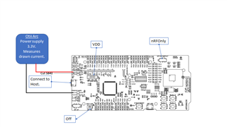
I like to understand what SBs should I cut, what switched should I use to measure the SOC current only with PCA10056 board.  I use the Otii Arc device to supply power to the pca10056 board. Since the Otii  measures the current taken from the it's power supply I need to connect it to P21 to measure current. So I do not have another device to measure current, just the Otii which does both. The user's guide for pca10056 did not explain this kind of set-up clearly, please guide me what shall I do.

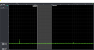
Now I have connected the Otti to P21 to supply power for the pca10056, the SW6 is set to  'nRF Only" state (SB40 is not cutted). Should I get SOC only current with this setup, or is there still some extra current drained by the external components?  By-the-way, can I connect power supply to P22 like it was guided in some instructions for pca10040 board (ref. case ID: 233961)?

Best Regards,

runner

Parents Reply Children
  • Thanks Jared,

    I followed your instructions in my measurements.

    For some reason the base-current is much higher than expected. It should be few uAs not tens of uAs like seen in the attachment. It looks that some interference is causing saw-wave which raise the avg base-current very high. Frequency of the saw-wave is 50Hz which indicates that it is coming from power supply for Otii Arc or though some other path. 

    However it is interesting why this is seen only with nRF52840-DK (pca10056) not with nrf52832 (pca10040).  The 840 board seems to be sensitive for interference e.g. if I press components on the board with my fingers it cause quite large envelope to the current consumption curve.

    Have you notice this and do you have ideas to make the 840-DK less sensitive for interference?

  • Hi,

    More observations. Obviously P21 is not good place to measure nRFonly current, there might be some grounding issues etc. that makes it sensitive for interference.

    I made new connections as shown in the attached picture.

    - Cut SB40.

    - SW6 to nRFOnly state

    - SW9 in VDD state

    - SW10 off 

    - Connect Otii's power supply's + wire to P22's upper pin (the pin closer to P23)

    - Connect Otii's - wire to P21's negative-pin.

    -  Connect J2 to host computer's USB

    => Now I started to get expected figures and the saw-wave disappeared.

    Your current measurement guide states in chapter  9 as follows: The current measurements will become unreliable when a serial terminal is connected to the virtual COM port."  Is this causing false figures in my new setup, to me they are in range at least?  Is there any ways to disconnect the serial terminal and still get reliable figures?  I tried to cut SB54, SB55, SB56 and SB57...did not help.


  • Hi,

    Usually we recommend connecting the connector J3 NRF_USB if the USB interface is used. However, we don't recommend connecting the J2 connector that powers the interface chip "due to added supply and measurement noise when the debugger chip USB port is active"

    runner said:
    For some reason the base-current is much higher than expected. It should be few uAs not tens of uAs like seen in the attachment. It looks that some interference is causing saw-wave which raise the avg base-current very high. Frequency of the saw-wave is 50Hz which indicates that it is coming from power supply for Otii Arc or though some other path. 

     What exactly is the application doing? Is the nRF in any power saving mode? Are you experiencing the same if you try to power it with a coin cell? What current do you measure if you program the DK with the power profiling application.

    regards

    Jared 

Related