This post is older than 2 years and might not be relevant anymore
More Info: Consider searching for newer posts

nr51822: No radio with custom PCB

Hi,

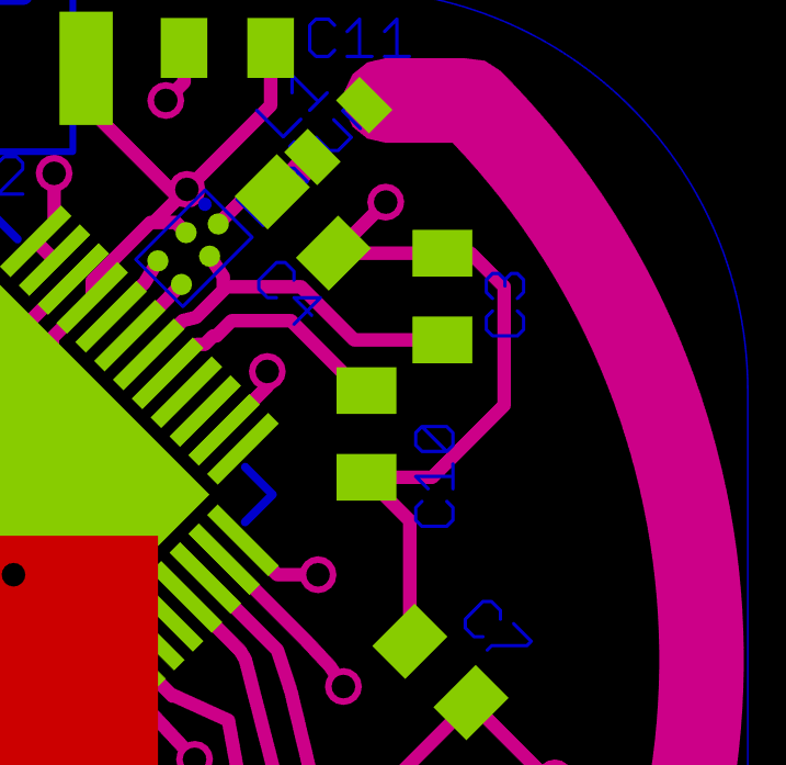
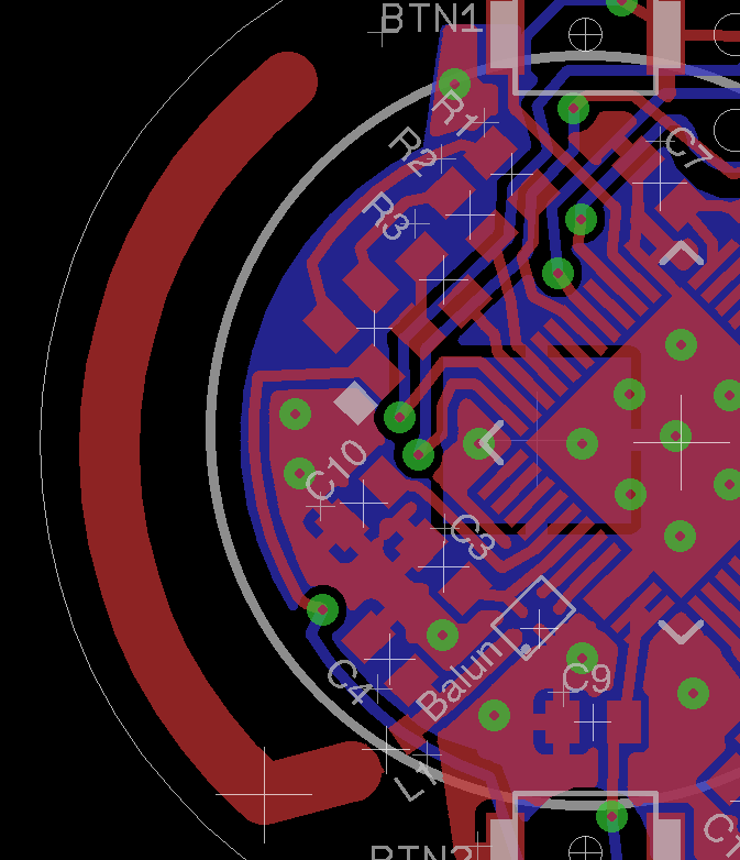
I have created a custom PCB that more or less follows the Nordic SmartBeacon design: Beacon_V2.pdf

Instead of BAL-NRF01D3 I used the BALF-NRF01D3 as this is supposed to be compatible with the QFAAG0 chips, which I use.

So now, when I load the SmartBeacon FW, everything seems to operate fine: LED pulsing, change to orange LED on button press (DFU mode)...

But what is missing is that I cannot capture any signal on my iPhone on the custom PCB... With the original Smart Beacon HW everything works fine. On the custom PCB I use the same shape and dimension PCB antenna.

I already switched from external 32Mhz crystal to internal but everything stays the same.

Now, how can I find out what is going wrong? Is there a way to see wether the soldering of the Balun was ok?

Thanks for your help!

Henry

  • image description

    Here a picture of how the balun is placed.

    Please let me know your comments

    Thanks

    EDIT: Attached please find a new version, this time with GND plane. Please let me know your comments, if this should be sufficient.

    image description

    Thanks, Henry

  • Hi Henry. To clarify: did you mean to write 32 kHz crystal or 32 MHz crystal? The nRF51822 requires a 16 MHz or 32 MHz crystal to operate the radio. A 32 kHz crystal is optional. In the case you're using a 32 MHz crystal this needs to be configured in firmware, because the default behavior is to assume the high frequency crystal is 16 MHz.

  • Hi Audun, Thanks for your comment. Sorry, my bad. I have the mandatory X1: 16MHz and the optional LF X2 with 32.768kHz. In order to see wether the soldering of X2 might be the problem, I did change the FW to use the internal clock and the result was the same, although you could see with the oscilloscope that X2 was not active in that case. So the LF crystal seems to operate fine.

  • It's difficult to tell from your screen shot, but it looks like the ground plane is missing, at least on the top top layer. Do you have a ground plane incorporated into your board? The antenna will not work as intended if there's no ground plane no the board.

    Secondly, if the ground plane is insufficient, you should still get a couple of inches of range. Could you test by holding the phone very close/on top/under the beacon and see if you get any readings at all out of it.

    I've recommended this as a debug option for many customer, it's to check the VDD_PA pin on the board. It will go up to 1.8 V when the chip is actually transmitting. So you should see that VDD_PA goes up to 1.8 V with an oscilloscope for every time you expect the beacon to send a package.

    You should also verify that the external 32/16MHz crystal is actually starting up.

  • Dear Asbjørn,

    Thanks for your comment.

    You are right, the GND pane is indeed missing and I will add this to my next design for sure. Could this mean that the antenna does not work at all? I tried to get as close as possible with both, phone and sniffer probe but did not receive any signal.

    I have check with the oscilloscope and was able to identify the 1.8 V peeks. So the chip does seem to transmit.

    In regards to the crystals: I was able to see the LF 32kHz crystal signal. But the 16MHz crystal I was not able to see anything on my oscilloscope. But also on the working Nordic Smart Beacon Board I was not able to measure the HF crystal... Can this mean that my pocket-oscilloscope is not sufficient?

Related